PathMaster® Manual Rev. H 6/03
- 58 -
Commands
NOTE: All programming tool procedures listed below are for FastPath™ only. Each path segment
taught corresponds to the valve selected in the FastPath™ toolbar.
Move
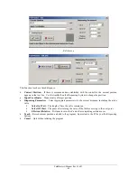
Click the Move Icon on the FastPath™ toolbar. Next click the location within the image where you would
like to move. The move form is displayed as normal. Make any modifications to the move location and
click the
Done
button. The
Cancel
button will cancel the creation of the move command.
Head
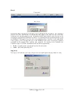
The head tool adds an appropriate pneumatics head command to the path program.
2D Line
The 2D Line tool creates a line less than or equal to 511 points. Click the 2D Line button to select the tool.
Next click all the points of the line on the image form. Each time a point is taught, the cursor will briefly
become a crosshair indicating that the point was registered. When you are done creating all points, right
click the mouse to complete the 2D Line. The 2 dimensional line will display on the board image with a
spray or dispense width equal to the area spacing parameter of the selected valve. The 2D line can be edited
graphically. See editing offline commands.
Arc
The Arc tool is created with two endpoints and a mid point. Click the Arc button to select the tool. Each
time a point is taught, the cursor will briefly become a crosshair indicating that the point was registered.
The arc will display on the board image as a complete circle. The playback of the arc will be the number of
degrees between the points.
Circle
The Circle tool is similar to the Arc tool except that a full circle is created with three points. Click the
Circle button to select the tool. Each time a point is taught, the cursor will briefly become a crosshair
indicating that the point was registered. The circle will display on the board image. You may edit the circle
by dragging any point of the circle to a new location. This will change the radius and location of the entire
circle. Dragging the center point does nothing. It is displayed for reference.
Area
The Area tool is created using three points. Click the Area button to select the tool. Click any three points
to generate an area command. The area command will behave as normal and the brush stroke will be from
point one to point two. The area pattern will progress one brush stroke at a time in the direction from point
two to point three.
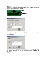
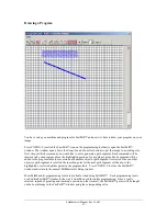
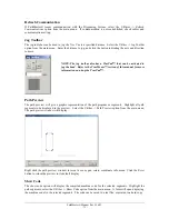
FastMask™
The FastMask™ tool is used to create a coating area followed by keep out areas within the coating area.
Click the FastMask™ button to select the tool. The first two point taught using FastMask™ define the
opposing corners of the coating area. After the coating area is defined, a dialog box will appear asking the
user to define the number of keep out areas within the coating area. A maximum of 99 keep out areas are
allowed. Enter the number of keep out areas and click OK. Teach the opposing corners of each successive
keep out area until the total number of keep out areas have been defined. The FastMask™ will display on
the board image as a blue coating area with red keep outs.
Summary of Contents for PVA2000
Page 9: ...Notes ...

