


Operation and Maintenance Manual Rev M(ii) 4/03
- 18 -
Operation
Startup Procedure
1) Check the fluid and air pressures.
2) Close all doors and turn the
DOOR BYPASS
key switch to the OFF position (If applicable).
3) Engage
the
EMERGENCY STOP
button.
4) Turn on main power using the red rotary switch at the front or rear of the machine (Black “rocker”
switch on PVA250™ models).
Light Tower Operation
Three stacked indicator lights and a buzzer are used to indicate the status of the machine. The lights are
green, amber, and red with green on the bottom, amber in the middle and red on top. The buzzer is located
below the green light. The lights are visible from all sides of the machine. The indicators operate as
follows.
o
The
green
indicator is on when the machine is in cycle and producing parts. It is off at all other times.
o
The
amber
indicator is on when the machine is in Auto Cycle and ready to produce parts, but can not
cycle due to an external material handling problem (no incoming parts or no room to unload parts).
PVA750™ and PVA2000C™ models are equipped with a light tower but not an amber light.
o
The
red
indicator is on steady when the machine is not in Auto Cycle due to operator intervention. It
will flash when the machine is in cycle, but cycle is halted due to a machine problem. It is off at all
other times.
o
The
buzzer
cycles with the red indicator during machine errors.
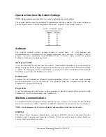
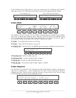
Table 4 – Light Tower & Buzzer Status
State Red
Amber
Green
Buzzer
Cycle Stop
ON
OFF
OFF
OFF
Auto Cycle
OFF
ON
OFF
OFF
In Cycle
OFF
OFF
ON
OFF
Machine Error
FLASH
OFF
OFF
FLASH
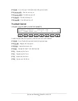
Exhaust Verification
Once the workcell has initialized, most models will perform an exhaust flow verification process. If
initialization fails, consult the section
on page 36. During this process, and whenever the
workcell is in operation the exhaust flow rate is monitored via the on board pressure differential switch.
The workcell must exhaust at a rate no less than 150 cubic feet per minute, otherwise a critical fault will
occur shutting the motors down. The verification process will also attempt to evacuate any potential vapors
that may already exist in the work area of the workcell. The time this process takes will vary from model to
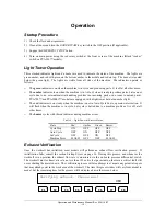
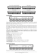
model, but the remaining time for the process will be displayed as in the screen below:
Verifying exhaust. Please wait ...
060
F1
F2
F3
F4
F5
F6
F7
F8
Summary of Contents for PVA2000
Page 9: ...Notes ...


