


Nixie Clock Kit ' Maestro’
ISSUE 1 (06 December 2012)
www.pvelectronics.co.uk
- 10 -
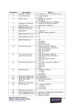
Parameter
Description
Values
0
Software revision
10 = version 1.0, 11 = version 1.1 etc
1
12 / 24 Hr mode
0 – 12 Hr (default)
1 – 24 Hr
2
Date format
0 = MM.DD.YY (default)
1 = DD.MM.YY
2 = YY.MM.DD (from V1.1 onwards)
3
Leading zero blanking
eg.
0
1:54:32
0 – leading zero blanked (default)
1 – leading zero displayed
4
Night Mode start hour
0 - 23
5
Night Mode end hour
0 - 23
6
Night Mode
0 – Tubes off
1 – Dimmed display (default)
7
Master Blank start hour
1
0 - 23
8
Master Blank end hour
1
0 - 23
9
Master Blank days
1
0 – Off
1 – Weekdays
2 - Weekends
3 – All days (default)
10
Colon neons mode
0 – AM/PM Indication, flashing
1 – AM/PM Indication, illuminated
2 – Both flash (default)
3 – Both illuminated
4 – Both off
11
Colon neons during
night dimmed mode
2
0 – AM/PM Indication, flashing
1 – AM/PM Indication, illuminated
2 – Both flash
3 – Both illuminated (default)
4 – Both off
12
Radio time signal source 0 – No Radio Time source (default)
3
1 – Reserved
2 – Reserved
3 – Reserved
4 - GPS
13
GPS Baud rate
0 – 4.8 Kbps (default)
1 – 9.6 Kbps
2 – 19.2 Kbps
3 – 38.4 Kbps
14
Radio time offset hours
0-13 (default 0)
4
15
Radio time offset mins
0-45 (default 0)
4
16
Radio time offset
polarity
0 - Minus time (default)
1 – Plus time
17
Reserved – leave as 0
0
18
Snooze period
0 – 6 minutes (default)
1 – 9 minutes
2 – 12 minutes
3 – 15 minutes
19
Reserved – leave as 0
0
20
Time Calibration Factor
0 - 99 (each unit adjusts by 0.2s per day)
21
Time Calibration Polarity 0 - Make clock slower
1 - Make clock faster


