


Nixie Clock Kit ' Maestro’
ISSUE 1 (06 December 2012)
www.pvelectronics.co.uk
- 7 -
4.
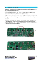
ASSEMBLY OF THE PCB
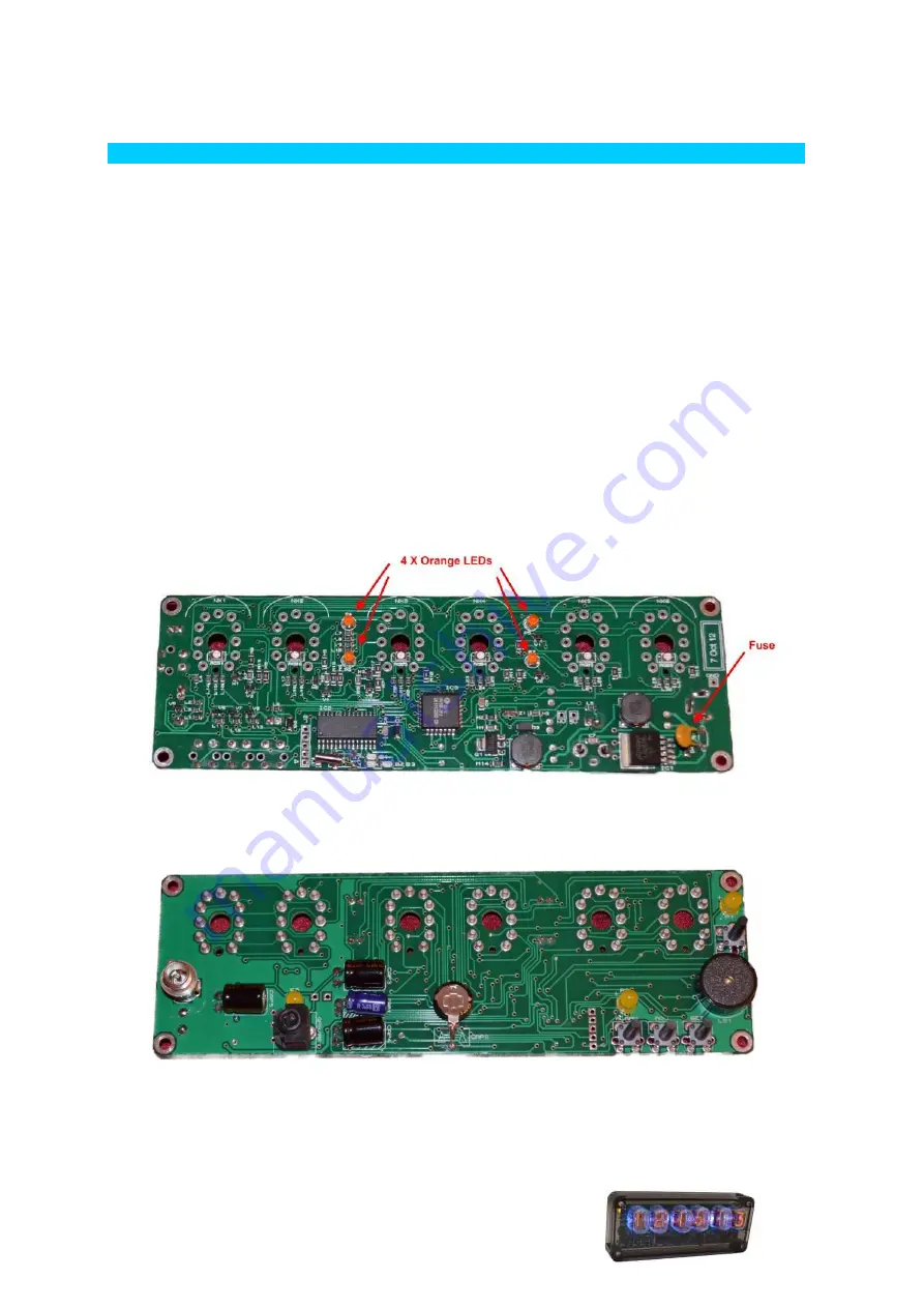
Assemble the components onto the front and rear of the PCB as shown in
the images below. Please note:
1. The longer lead of the LEDs is the '+' lead. this goes into the hole
marked '+' or the hole with the white circle around it.
2. The electrolytic capacitors are polarised. The side of the capacitor with
the lighter band marked '-' goes next to the cross-hatched marking on
the PCB.
3. CAP2, the time backup capacitor, needs to be placed flat against the
PCB. Use a small length of trimmed lead from another component to
extend one lead so that it can be place flat. Also note the arrows on the
PCB match the arrows on the part.