CONQUEST
®
WATER HEATER
28
PV500-71 02/16
Sidewall Termination for Multiple
Horizontal Concentric Vent
Wall Termination
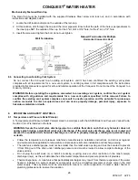
Mechanically Fastened Rain Cap
The Rain Cap must be installed with the supplied Stainless Steel screw and lock nut, and in accordance with
instructions and diagram below.
1. Locate the drill location dimple on the outside of the rain cap.
2. At this location, drill through the cap and the inner pipe wall. Ensure that the path of the hole is perpendicular to
the inner pipe NOT the outside of the cap. For the 3" kit, drill a 3/16" hole, for the 4" kit, a 1/4" hole.
3. Insert the screw and tighten the bolt, do not over tighten.
8.6 Connecting to an Existing Vent System
Do not connect the Conquest to an existing vent system, until it has been confirmed the existing vent system
complies with all requirements for a new vent system. A venting system in full compliance with the instructions
provided in this manual is required for safe and reliable operation of the Conquest. Do not connect the Conquest to a
masonry chimney
.
WARNING: Before operating the appliance connected to an existing vent system, confirm the vent system
complies with all guidance and requirements for a new vent system specified in this manual. Failure to
confirm the existing vent system complies can result in unsafe operation and the potential for poisonous
carbon monoxide to enter occupied areas and can cause property damage, personal injury, exposure to
hazardous materials or death.
9.
OPERATING AND SAFETY CONTROLS
9.1 Temperature and Pressure Relief Valve(s)
A Temperature and Pressure Relief Valve(s) sized in accordance with the ASME Boiler and Pressure Vessel Code,
Section IV HLW is installed in the tank.
WARNING: Secure the relief valve discharge pipe to a suitable floor drain such that very hot water does not
openly splash during a significant relief valve discharge. If the relief valve discharge pipe is not routed and
secured to a suitable drain, hot water discharge can result in property damage, scalding and personal injury
or death.
•
Follow the temperature and pressure relief valve manufacturer’s installation instructions and all local, regional
and national codes applicable to temperature and pressure relief valve installation and discharge piping.
•
The relief valve discharge pipe must not be smaller than the relief valve opening and must be secured to prevent
it from lifting out of the drain under discharge pressure and must be routed to allow complete drainage of the
valve and line.
•
Do not plug the relief valve (s) or install a reducing coupling, valve or other restriction in the relief valve(s)
discharge line(s), as this will eliminate the critical water temperature and pressure protection it provides.
•
Thermal Expansion - A relief valve that periodically discharges may result from thermal expansion if the water
heater is installed in a system closed by components, such as a backflow preventer or check valve in the cold
water supply. These systems must be provided with means to control expansion. Contact a water heater or
plumbing professional to resolve this situation.

