POWER VTX
®
WATER HEATER
20
PV500-68 06/16
8. Vent support – For PVC or CPVC, the vent system must be supported at intervals no greater than four feet, to
prevent sagging, distortion and stress on pipe fittings. Vertical pipe must also be supported to avoid stress on all
cemented pipe fittings and to prevent putting excessive weight on the appliance vent connection. For listed
stainless steel or polypropylene vent system, follow the vent system manufacturer’s instructions.
9. Testing for leaks – Once the vent system is installed, it must be checked to confirm all joints in the vent system
are air and water tight. After the vent is assembled, close the end of the vent with a taped plastic bag or some
other temporary closure. With the gas supply turned off, energize the POWER VTX
®
combustion blower to
apply air pressure to the vent system. Spray each joint and vent connection with commercially available leak
detection liquid to confirm no air is escaping from any point. Repair any leaks and retest. After testing is
complete, de-energize the combustion blower, wipe clean the leak detection liquid and REMOVE the temporary
vent closure.
10. The vent pipe must be sealed at the point where it passes through a wall or roof, to prevent rain, insects or flue
products from entering the living space or interior of the building.
11. For proper vent operation and to protect the gas vent from wind and weather,provide suitable termination to
prevent wind, water, debris or animals from obstructing or entering the vent.
12. Do not use a barometric damper with the POWER VTX
®
venting system. Barometric dampers are designed for
use with certain Category I negative pressure vent systems. The POWER VTX
®
uses certain Category IV
positive pressure vent systems and will not operate safely with a barometric damper.
WARNING: Use only solid PVC or CPVC pipe or use Polypropylene or stainless steel venting (single or
double wall) listed by a nationally recognized testing laboratory for Category IV positive pressure gas
appliance venting. Use of ABS pipe, or use of PVC or CPVC pipe with cell/foam type construction or use of
use of venting materials other than specified in these instructions can result in failure of the venting system
and/or exposure to carbon monoxide or other toxic fumes, which can result in property damage, personal
injury or death.
WARNING: Do not vent this water heater into an existing or traditional gas vent or chimney, do not combine
the vent with any other appliance and do not use a barometric damper in the vent. Such venting could result
in failure of the venting system and/or exposure to carbon monoxide which can result in property damage,
personal injury or death.
8.2 Maximum Vent Length
(Equivalent Length)
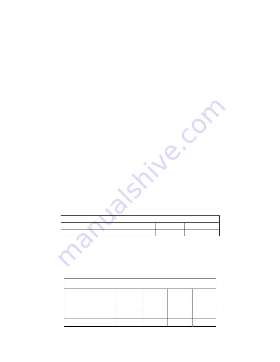
The maximum length of field supplied Category IV vent is shown in the chart below:
Maximum Allowable Equivalent Vent Length / Max Elbows
Duct Size
6
″
Duct
8
″
Duct
Max Equivalent Length all Models
230 feet/9
350 feet/9
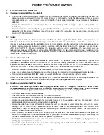
Pipe fittings reduce the maximum allowable vent length. Use the Category IV vent manufacturer’s equivalent length
deduction for all elbows, terminations, etc. If the information is not readily available from the vent manufacturer, use
the Vent Fitting Equivalent Length chart below to find the total equivalent length for all vent fittings in your
combustion air system. Then subtract this number of feet from the total equivalent length allowed in Maximum
Category IV Vent Equivalent Length chart above. The sum of this calculation is the maximum length of straight vent
allowed. If a longer length is required, repeat the calculation using a larger vent size. When using this chart, no
additional deduction is required for the addition of the vent system terminal.
Vent Pipe Fitting Equivalent Length for all Models
Vent Pipe:
PP *
6
″
Vent
Other **
6
″
Vent
PP *
8
″
Vent
Other **
8
″
Vent
90º Elbow
22 feet
20 feet
11 feet
10 feet
90º Long Radius Elbow
14 feet
12 feet
5 feet
6 feet
45º Elbow
14 feet
12 feet
5 feet
6 feet
* PP = polypropylene
** Other = PVC, CPVC or Stainless Steel


