POWER VTX
®
WATER HEATER
35
PV500-68 06/16
11.6 Flame Current Measurements
The PIM supports direct measurement of flame signal strength using the flame current test pins (FC+, FC-) on
connector P2. Flame current may be measured by a micro-ammeter, or alternately by using a standard digital
voltmeter. The signal on P2 is calibrated to 1 micro-amp/volt, so flame current in micro-amps can be directly read on
the volts scale.
The control display user interface is capable of displaying an approximation of flame current up to 5 micro-amps
.
11.7 Non-Volatile Lockout / Manual Reset
The PIM normally allows for volatile ignition lockout where a lockout condition is reset by a loss in 24VAC power or
the call for heat demand. In certain applications or where required by standards (such a CSD-1), it can be
configured through the parameter settings for non-volatile lockout after ignition failure. In this case the lockout may
only be reset by the on-board manual reset button, or the remote reset input.
11.8 ID Card
The PIM determines its operating parameters by reading the identification code of an external plug-in ID card. The
ID card is connected to the PIM at the J6 connector.
NOTE
: This ID card must be present for the PIM and appliance to operate. This card selects the proper settings in
the PIM's memory for various appliance models. The first time a PIM is powered up attached to an ID card, the ID
card setting is stored in non-volatile memory. Once set, the PIM only operates with the correct ID card installed that
matches its internal ID settings. The PIM verifies the ID card at power-up and on each heating cycle
12. NETWORK
MENU
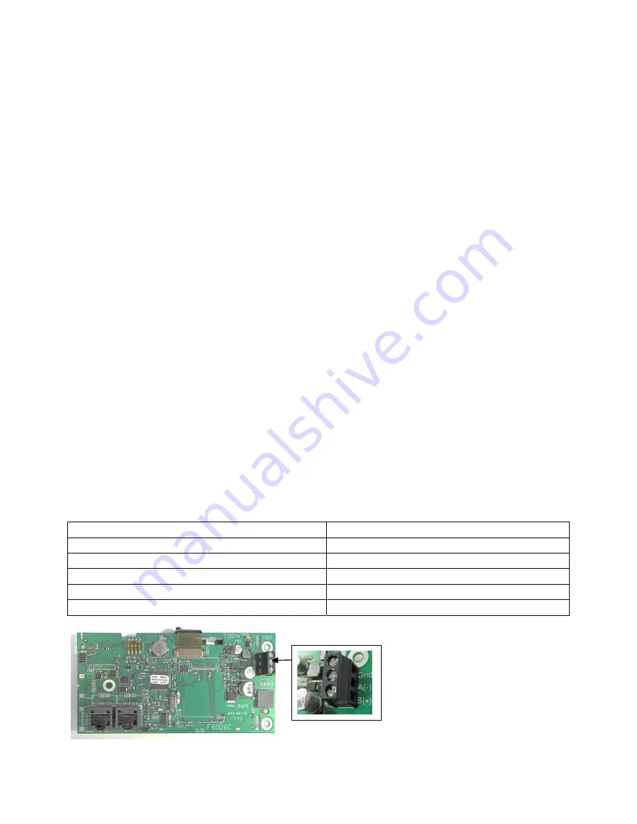
The Network Menu contains all of the settings necessary to configure a 2-wire, RS-485 communication link with this
product. With no additional hardware, a Modbus RTU or ASCI protocol can be established.
1. Enter the Network Menu as previously explained. The first screen, ADDRESS, will allow the user to set the
network address for each individual heater. There are up to 247 addresses beginning with number 1. If there
are multiple heaters in the network, each heater should have a unique address. The default value 1.
2. The second screen, DATA, sets the data format. Select between RTU (8bit) and ASCI (7bit).
3. The third screen, BAUD RATE, 2400, 9600, 19K2, 57K6 and 115K.
4. PARITY, will select between NONE (2 Stop bits), EVEN (1 Stop bit) and ODD (1 Stop bit).
5. The table below details wire length using 18 AWG Shielded Twisted-Pair.
Max Cable Length Without Terminating Resistors
Max Cable Length with 2 x 120 Ohm Resistors
•
115200 baud --> 177 m (580 ft)
•
115200 baud --> 1,000 m (3,280 ft)
•
57600 baud --> 353 m (1,158 ft)
•
57600 baud --> 1,000 m (3,280 ft)
•
19200 baud --> 1,000 m (3,280 ft)
•
19200 baud --> 1,000 m (3,280 ft)
•
9600 baud --> 1,000 m (3,280 ft)
•
9600 baud --> 1,000 m (3,280 ft)
•
2400 baud --> 1,000 m (3,280 ft)
•
2400 baud --> 1,000 m (3,280 ft)
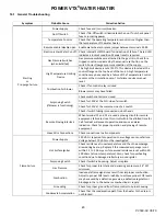
Connect RS-485 wires here. If
you are unable to establish a
connection reverse the + & -
wires.


