background image

POWER VTX

® 

WATER HEATER


55 

PV500-68  06/16


Summary of Contents for Power VTX 100 L 225 A-PVX

Page 1: ...D AND FOLLOW THE INFORMATION IN THIS MANUAL AND ALL OTHER PROVIDED INSTRUCTIONS LABELS AND MARKINGS BEFORE INSTALLING OPERATING OR SERVICING THIS UNIT TO THE INSTALLER After installation these instructions must be given to the equipment user or left near the appliance SPECIAL INSTRUCTIONS TO THE OWNER Retain this manual for future reference These instructions contain important information that wil...

Page 2: ...pply and Piping 6 1 Gas Train and Controls Certification 6 2 Gas Control Trains 6 3 Inlet Pressure 6 4 Manifold Pressure 6 5 Gas Piping Size 6 6 Appliance Isolation During Gas Supply Piping Pressure Test 6 7 Gas Connection 7 Combustion and Ventilation Air 7 1 Equipment Located in Confined Spaces 7 2 Maximum Allowed Remote Combustion Air Inlet Length 7 3 Remote Combustion Air Termination 7 4 Vertic...

Page 3: ...fety Checks 11 6 Flame Current Measurements 11 7 Non Volatile Lockout Manual Reset 11 8 ID Card 12 Network Menu 12 1 EOS Register List 12 2 Error Codes 13 Remote Connections Terminal Strip 13 1 Making BMS BAS Remote Connection for Analog and Binary Signals 13 2 Terminal Functions 14 Sequence of Operation 15 Initial Startup 15 1 Initial Startup Requirements 15 2 Tools and Instrumentation Required 1...

Page 4: ...product contains or may come to contain materials that have been identified as carcinogenic or possibly carcinogenic to humans Before installing servicing or removing this product read and follow the supplied instructions Clearance in accordance with the local installation codes and the requirements of the gas supplier Dégagement conforme aux codes d installation locaux et aux exigencies du foumis...

Page 5: ...ontrols Use NIOSH MSHA approved respirators as required see MSDS Wear long sleeved loose fitting clothing eye protection and gloves FIRST AID MEASURES If any of the irritations listed persists seek medical attention Eyes Flush with water Skin Wash with soap and warm water Ingestion Do not induce vomiting Get medical attention if gastrointestinal symptoms develop Inhalation Remove to fresh clean ai...

Page 6: ...PHYSICALLY HANDICAPPED HOSPITALS AND NURSING HOMES ELDER CARE FACILITIES AND REST HOMES ORPHANAGES AND CHILD CARE FACILITIES OTHER INSTALLATIONS WHERE RESPONSE TO CONTACT WITH HOT WATER MAY BE SLOWER OR WHERE THE DANGER OF HOT WATER CONTACT IS GREATER Thermostatically controlled mixing valves must be used in the design of the potable hot water system Potable hot water should be tempered to no more...

Page 7: ...POWER VTX WATER HEATER 7 PV500 68 06 16 2 PRODUCT DESCRIPTION Component Controls and Connection Locations Locations May Vary ...

Page 8: ...onform to local electrical codes and or CSA C22 1 Canadian Electrical Code Part 1 All wiring between the unit and field installed devices must be made with type T copper wire Line voltage wire exterior to the appliance must be enclosed in approved conduit or approved metal clad cable To avoid serious damage DO NOT energize the unit until the system and appliance is full of water Utiliser du fil de...

Page 9: ...ENERAL PIPING GUIDELINES 4 1 Inlet and Outlet Connections 1 Use only non ferrous water piping and fittings When connecting to the POWER VTX tank there is no requirement to use di electric nipples and they are not recommended Also do not use galvanized or steel pipe or fittings Over time rust can form inside of steel galvanized or di electric pipe nipples or fittings 2 Install shut off valves and u...

Page 10: ...POWER VTX WATER HEATER 10 PV500 68 06 16 SINGLE WATER PIPING SINGLE STORAGE WATER HEATER WITH SUPPLEMENTAL STORAGE TANK ...

Page 11: ...POWER VTX WATER HEATER 11 PV500 68 06 16 TWO WATER HEATERS WITH REVERSE RETURN PIPING ...

Page 12: ...sition 90 degrees from the floor NOTE Additional CPVC fittings and pipe can be added to the condensate drain connection to relocate the condensate trap assembly as long as all added parts are at the same elevation of the condensate drain connection IMPORTANT Do not rotate the condensate drain connection toward the ceiling Do not use tools to tighten the CPVC union Hand tighten the CPVC union to se...

Page 13: ...convenient place between the condensate outlet and a suitable drain and where the 3 threaded end cap can be removed to recharge the Neutralizer with crushed limestone a The CNS must be located such that condensate will flow downhill from the condensate trap outlet to the inlet on one end of the CNS and downhill from the other end of the CHS to the drain If this continuous downhill flow is not main...

Page 14: ...in property damage personal injury or death 6 3 Inlet Pressure Measure at the inlet pressure tap located at the main gas cock The inlet pressure must remain within the minimum and maximum values while the unit is at rest and while the unit is operating at maximum firing rate 6 4 Manifold Pressure Measure at the pressure tap located downstream side of the manual valve closest to the burner The rate...

Page 15: ...ing connected to the appliance to isolate the burner and gas train from main supply gas in compliance with NFPA 54 National Fuel Gas Code and most local Codes 6 The gas system installer must clearly identify the emergency shut off device 7 A sediment trap drip leg MUST be provided in the inlet of the gas connection to the unit 8 The combination gas valve incorporates an internal vent limiter Venti...

Page 16: ...ea of 1 square inch per 2000 Btu hr of the total input rating of all appliances in the enclosure if communicating with the outdoors through horizontal ducts All Air From Inside The Building Follow the requirements of NFPA 54 National Fuel Gas Code ANSI Z223 1 section Indoor Combustion Air Combination Of Air From The Indoors And From The Outdoors Follow the requirements of NFPA National Fuel Gas Co...

Page 17: ...size No additional deduction is required for the addition of the duct system terminal Duct Pipe 6 Duct 8 Duct 90º Elbow 20 feet 10 feet 90º Long Radius Elbow 12 feet 6 feet 45º Elbow 12 feet 6 feet The following remote air duct information is provided for use in design calculations if needed Remote Air Duct Specifications Input MBtu h Required Air SCFM 500 110 750 165 1000 220 7 3 Remote Combustio...

Page 18: ... and regulating positive pressure air supplied to all water heaters in the system The pressure of the supplied air must not be less than 0 0 W C and must not exceed 0 25 W C The common combustion air supply system must be interlocked so the water heaters will not begin operation until the common combustion air supply is proved to be within the range of 0 0 to 0 25 W C See Section on Remote Connect...

Page 19: ...he water heater vent connection with at least inch drop per linear foot of horizontal vent run to allow proper drainage of accumulated condensation All penetrations through walls and roofs must be weather and gas tight such that rain and products of combustion cannot pass from outdoors back indoors Additional steps required when venting with solid PVC or CPVC pipe 1 Read and follow the information...

Page 20: ...double wall listed by a nationally recognized testing laboratory for Category IV positive pressure gas appliance venting Use of ABS pipe or use of PVC or CPVC pipe with cell foam type construction or use of use of venting materials other than specified in these instructions can result in failure of the venting system and or exposure to carbon monoxide or other toxic fumes which can result in prope...

Page 21: ...ent must extend one foot beyond the wall 8 A horizontal vent terminal must not be installed closer than 3 feet 0 91m from an inside corner of an L shaped structure 9 A vertical vent must exhaust outside the building at least 3 feet 0 91m above the point of the exit and at least 2 feet 0 61 m above the highest point of the roof within a 10 foot 3 05 m radius of the termination 10 A vertical termina...

Page 22: ... a qualified professional firm and that meets all the requirements contained in Subsection Combining Remote Air Ducting which is located in the COMBUSTION AND VENTILATION AIR Section of this manual WARNING Do not connect multiple water heaters vents into a single unpowered or fixed speed powered vent This could cause unsafe operation and the potential for poisonous carbon monoxide to enter occupie...

Page 23: ...th 9 2 Cathodic Protection PVI water heaters do not utilize cathodic protection However in hot water systems utilizing cathodic protection hydrogen gas can be produced when the hot water system has not been used for a long period of time generally two weeks or more Hydrogen gas is extremely flammable To prevent the possibility of injury under these conditions one of the hot water system faucets sh...

Page 24: ...ûlures ou la mort de brûlures Suivez les instructions dans le manuel d installation pour modifier la température de l eau 9 5 High Water Temperature Limit The water heater Electronic Operating Control System EOS includes a single probe that contains a high water temperature limit and a completely separate upper tank operating sensor Since both these sensors are in the same location in the heated s...

Page 25: ...ing an RJ485 patch cable All communication between the PIM and control display as well as the power to the control display is through this cable Platform Ignition Module PIM ID Card Flame current test pins ID card plug J6 Reset Potentiometer 2amp Fuse Indicator LEDs Home Button Home Button Return to the Home Screen from any menu Press and hold for 3 seconds to access the programming menus Digital ...

Page 26: ...ride Menu IDLE The EOS is Idle due to no demand for heat ARSW The EOS is attempting to purge but waiting for the air proving switch to prove blower air flow PREP The EOS is Pre Purging the burner system IGN The Hot Surface Igniter is hot and the gas valve has opened to attempt burner ignition 4 seconds BURN The Burner has ignited and the flame has been sensed POST The Call for Heat has ended and t...

Page 27: ...lue gas sensor located in the flue outlet TANK TOP Displays the current temperature at the top of the water heater tank as measured by the operating control sensor located near the hot outlet TANK BOT Displays the current temperature near the bottom of the water heater tank as measured by the control sensor responsible for regulating the operation of the integral tank circulator TANK T Displays th...

Page 28: ...or details Control System Menu Descriptions Menu Description SETUP Displays and modifies the temperature control set points for the burner integral tank circulator and the SANI functions SOURCE Displays many factory programmed settings for this product The settings which can be adjusted by the user will be indicated by the appearance of the up and down adjustment arrows MONITOR Displays operationa...

Page 29: ...the NEXT ITEM or BACK ITEM buttons or when exiting the menu by pressing the HOME button 10 7 Setting the Real Time Clock User Installer Level Access The TIME MENU allows the user to program the time of day the date and the year A 12 or 24 hour time clock as well as daylight saving time can be selected When selected the time clock can be displayed in the VIEW MENU 1 Press and hold the Home button f...

Page 30: ... event day schedule might look like this The 1st occupied time begins at 6 00am and the 1st unoccupied time begins at 11 00am therefore between the hours of 6 00am and 11 00am the occupied set point will be used The 2nd occupied period begins at 4 00pm and the 2nd unoccupied time begins at 10 00pm Between the 1st unoccupied time of 11 00am and the beginning of the 2nd occupied period the unoccupie...

Page 31: ...ring rate This function is useful when tuning the operation of the burner at a range of firing rates NOTE If the HTR MOD control is activated while the burner is firing the burner will shut down and recycle WARNING When adjustments are complete and before putting the water heater into service return the MAN OVR function back to AUTO Failure to return the MAN OVR function to AUTO can cause high wat...

Page 32: ...quiring an ADVanced access level Depending on the access level selected different parameters will become visible and adjustable Selecting the appropriate access level will make menu navigation easier and minimize the possibility that parameters will be unintentionally changed resulting in improper operation 2 The second screen will display the software revision for the touch panel display Press th...

Page 33: ...ing rate to prevent overheating N A 5 AIR FLOW FAIL During blower purge periods the air flow proving switch is not closing this circuit This could be caused by a faulty blower or pressure switch 1 9 FLAME FLSE A false flame signal is usually cause by a leaky gas valve which propagates a flame after the call for heat cycle has ended Check for leakage through the gas valve If no mechanical cause can...

Page 34: ...with the top temperature sensor possibly a broken or shorted sensor wire or failed sensor NOTE The top sensor and the high limit sensor or located in the same probe body 8 11 HI LIMIT Indicates a problem with the high limit temperature sensor possibly a broken or shorted sensor wire or failed sensor NOTE The top sensor and the high limit sensor or located in the same probe body 8 14 HTR BOT Indica...

Page 35: ... PIM is powered up attached to an ID card the ID card setting is stored in non volatile memory Once set the PIM only operates with the correct ID card installed that matches its internal ID settings The PIM verifies the ID card at power up and on each heating cycle 12 NETWORK MENU The Network Menu contains all of the settings necessary to configure a 2 wire RS 485 communication link with this prod...

Page 36: ...e Read Input S16 F 22 to 266 111 Modulation Rate Read Input U16 0 to 100 112 Flame Current Read Input U16 0 1V 0 10 0 113 Burner Runtime Read Input U16 Hours 0 65535 114 Burner Cycles Read Input U16 Num 0 65535 115 Heater Circulator Status Read Input U16 Enum 0 Off 1 On 116 Heater Setpoint Occupied Read Write Holding S16 F 70 to 190 200 Heater Setpoint Unoccupied Read Write Holding S16 F 70 to 190...

Page 37: ...oiler Outlet Tank Top Sensor 12 Boiler Inlet Tank Bottom Sensor 13 Vent Sensor 14 Hi Limit Sensor 15 Ignition Failure 16 Flame Loss 17 Vent Hi Limit 18 Boiler Tank Hi Limit 19 False Flame 20 OEM Card 21 Internal Failure 22 Hi Delta 23 Low HSI 24 Low Voltage 25 Blower Speed 26 High Gas Pressure tN4 Errors This series of errors are related to the communication links between multiple heaters in a lin...

Page 38: ...uit ampacity rating R1 R2 Used to activate de activate water heater from remote master control Terminals are wired to a relay in a remote Energy Management System When the relay closes the circuit from R1 to R2 is completed and appliance controls are enabled This appliance ships from factory with a jumper between terminals Remove jumper when connecting to a remote controller A1 A2 Used to activate...

Page 39: ...gh Temperature Limit is combined in a common probe body with the upper tank sensor The PIM will compare the high limit thermistor temperature with the upper tank thermistor temperature If the two temperatures are not the same a sensor failure will result d When the High Temperature Limit operation has been verified by comparison the limit temperature will then be confirmed to be under the maximum ...

Page 40: ...eeds to Standby mode 8 Integral Circulating Pump The circulating pump is controlled independently of the call for heat a When the main control switch is turned on the control system will continuously monitor the water temperature in the tank and attempt to maintain a uniform water temperature within the tank by using the integral circulating pump b If the temperature sensed in the tank drops 5 deg...

Page 41: ...aft Gauge Electronic Combustion Analyzer Two U tube Manometers or pressure gauges AC DC Multi meter with 20 000 OHM Volt rating Amp Meter Normal Hand Tools 15 3 Resources Product Installation Maintenance Manuals Start up Report with instructions Local State Federal Codes Website www pvi com Technical Support 1 800 433 5654 15 4 On Site Considerations Electrical Supply in accordance with the Namepl...

Page 42: ...a test meter to the ignition control to read the flame current in microamps NOTE Some flame controls read the flame signal in micro amps and some in volts DC 10 Check the inlet gas pressure before start up using a manometer or a 0 to 28 W C pressure gauge for inlet gas pressure This is the pressure measured before all components in the gas train This manometer must stay connected throughout the te...

Page 43: ... burner firing adjust the valve orifice screw counter clockwise to increase gas flow or clockwise to decrease flow The desired CO2 in the combustion products must be between 8 5 and 9 5 for natural gas and between 9 5 to 10 5 for LP gas Do not attempt to adjust combustion based on manifold pressure alone Manifold pressure should only be used as a reference point It should not be necessary to adjus...

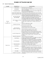
Page 44: ...or or erratic ground Follow the Initial Startup instructions in section 15 as the first step in any troubleshooting Verify that the system is powered and that the thermostat is calling for heat If the control displays an error code on the red diagnostic LED troubleshoot per Section 11 2 Alarm Messages Diagnostic Codes The LED will flash on for 1 10 second then off for 2 5 second during a fault con...

Page 45: ...re closed Check for 120V at the N O side of air switch Check for 120V at the common side of air switch Check if switch tubing is connected on both ends Remote Proving Interlock When terminal C1 and C2 are used a proving circuit for remote equipment failure to close this circuit within the allotted time for Call for Heat will prevent operation and cause an alarm indication Check for proper operatio...

Page 46: ... Low Voltage Fault 5 flashes Check the 24 VAC input voltage The voltage must be above 18 0 VAC Vent Temperature Fault 6 flashes Check for a blocked flue Check the vent sensor and connections Hi Limit Fault 7 flashes Check for proper water flow Check hi limit and outlet sensors Sensor Fault 8 flashes See the digital control display for fault identification Check sensors and wiring Safety 1 Fault 9 ...

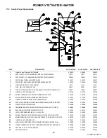
Page 47: ...126863 126863 5 INTAKE AIR DUNGS WHIRLWIND 255951 126864 6 ADAPTER FLEXIBLE RUBBER 6 X 4 126850 126850 6 ADAPTER FLEXIBLE RUBBER 6 X 5 126849 7 GASKET BLOWER OUTLET 5 500 SQUARE AMORIM CR 55R 1 8 CORK 126866 126866 7 GASKET BLOWER OUTLET 7 100 SQUARE AMORIM CR 55R 1 8 CORK 126867 8 TAB BURNER GROUNDING 128315 128315 128315 9 GASKET FLANGE BURNER 1 8 232 CRANEGLAS 5 750 ID 126509 126509 126509 10 G...

Page 48: ...22346 11 BLOCK TERMINAL WAGO 280 833 600V 20A DIN 122319 122319 122319 12 JUMPER TERMINAL BLOCK WAGO 280 402 23A 122320 122320 122320 13 SWITCH AIR PROVING CLEVELAND CONTROLS NS2 1166 01 0 50 WC 121444 121444 121444 14 FLAME CONTROL PIM FENWAL 126088 126088 126088 15 TRANSFORMER STEP DOWN TRIAD F5 24 115VAC 24VCT 12 0VA 126865 126865 126865 16 BAR GROUND SQUARE D PK5GTA 5 POLE 122321 122321 122321...

Page 49: ...2 120VAC 109884 109884 109884 2 VALVE SHUTOFF 1 GAS COMBU 55350 MODEL 840S 52823 52823 52823 3 UNION BLACK 1 5929 5929 5929 4 NIPPLE BLACK 1 X 2 6011 6011 6011 5 NIPPLE BLACK 1 X 3 6012 6012 6012 6 NIPPLE BLACK 1 X 9 6020 6020 6020 7 ELL BLACK 90DEG 1 6163 6163 6163 8 SHUTTER FLANGE 1 DUNGS 255132 126862 126862 126862 9 FLANGE VALVE 1 DUNGS D221999 110308 110308 110308 ...

Page 50: ...FLANGE MTG BRONZE INTEGRAL PUMP PL 2 SIDE RAD SB584 UNS 119301 119301 119301 2 MOTOR PUMP B G 1BL113 MODEL PL 75 115 VAC W IMPELLER 120090 120090 120090 3 O RING GASKET 4 25 OD X 3 50 ID X 375 CS EPDM 80 DUROMETER 122423 122423 122423 4 VALVE BALL 1 SMITH COOPER 01728135K BRASS THREADED 123333 123333 123333 5 VALVE T P RELIEF 1 WATTS 140X 6 150 PSI 670 M 3085 709 709 709 ...

Page 51: ...POWER VTX WATER HEATER 51 PV500 68 06 16 17 5 Component Wiring and Conduit Routing Details ...

Page 52: ...roperly installed and adjusted units seldom need heat exchanger cleaning If soot has formed the most common causes are restricted combustion air or excessive gas A blocked heat exchanger can cause unsafe operation and will reduce efficiency To inspect and clean the heat exchanger a qualified service agent or installer should use the procedures described in items 4 5 6 below 4 All gaskets on disass...

Page 53: ...de or Table 10 8 for information about operation of the pump 7 Inspect low water cutoffs and relief valves for proper operation at every six months or more often if indicated by inspection 8 Keep appliance area clear and free from combustible materials gasoline and other flammable vapors and liquids 9 Check frequently to be sure the flow of combustion and ventilation air is unobstructed to the app...

Page 54: ...ctions 7 Inspect burner and gas train components for wear or deterioration 8 Check the electronic ignition system for quick ignition and proper flame signal 9 Check gas safety shut off valves for proper operation and tightness 10 Follow startup procedure in the Installation Maintenance Manual Semi Annually Every Six Months 1 Test Low water cut off if equipped Refer to manufacturer s instructions a...

Page 55: ...POWER VTX WATER HEATER 55 PV500 68 06 16 ...

Page 56: ... the warranty on the heat exchanger does not cover poor performance structural failure or leaking due to an excessive accumulation of scale Warranty Forms Ship Separately With Each Product MODEL NUMBER SERIAL NUMBER INSTALLATION DATE PVI INDUSTRIES LLC 3209 Galvez Ave Fort Worth Texas 76111 Phone 1 800 433 5654 www pvi com ...

Reviews: