s.r.l.
pompe per vuoto
EU 205 - EU 205/B EU 300 - EU 300/B
11
5.4 Collegamento alla macchina utilizzatrice
Il collegamento della pompa alla camera da evacuare deve essere
eseguito con tubazioni dello stesso diametro della bocca di aspirazio-
ne. Il peso delle tubazioni e le eventuali dilatazioni non devono gravare
sulla pompa. Si consiglia di effettuare il collegamento finale alla
pompa con tubi o raccordi flessibili. E' importante che tutte le tubazioni
ed i vari giunti siano a tenuta. Tubazioni molto lunghe o di diametro
piccolo diminuiscono le prestazioni della pompa.
5.5 Convogliamento aria di scarico
❑
In caso di necessità è possibile convogliare l'aria di scarico della
pompa in altri ambienti o all'esterno.
❑
Utilizzare tubazioni di diametro uguale alla bocca di scarico del
serbatoio per una lunghezza massima di 15 m.
Per lunghezze superiori aumentare il diametro del tubo. Il peso delle
tubazioni non deve gravare sulla pompa.
Utilizzare nel tratto finale raccordi o tubi flessibili.
AVVERTENZE
:
questa tubazione deve essere discendente per evitare il rientro di
condensa nel serbatoio della pompa.
Non inserire rubinetti in questa tubazione.
5.6 Collegamento elettrico
❑
Il quadro di comando e l'allacciamento elettrico devono essere
effettuati da personale specializzato secondo la norma EN 60204-1 o
altre normative vigenti nel paese d'utilizzo.
❑
Gli equipaggiamenti elettrici devono essere conformi alle norme EN
61000-6-4 e EN 61000-6-2 riguardanti la compatibilità elettromagne-
tica, emissione ed immunità per ambiente industriale.
❑
Verificare la tensione e la frequenza di rete con i dati riportati sulla
targhetta del motore.
❑
Il motore elettrico deve essere protetto da sovraccarichi.
Utilizzare il valore di assorbimento elettrico riportato sulla targhetta
motore come riferimento.
❑
Assicurarsi dell'efficienza dell'im-
pianto di messa a terra.
❑
Eseguire l'allacciamento elettrico
seguendo lo schema riportato sulla
morsettiera del motore.
❑
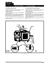
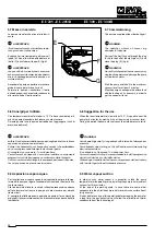
Controllare il senso di rotazione
del motore accendendo la pompa
per un breve istante (
2-3 secondi). Il
senso corretto è quello indicato dal-
la freccia posta sulla pompa (
fig.5).
Nel caso di rotazione contraria, oc-
corre invertire il campo di rotazione
del motore cambiando posizione a
due dei tre conduttori di fase alla
morsettiera di cablaggio del motore.
5.4 Connection to the using machine
The connection to the chamber to be pumped down must be carried
out by means of pipes of the same diameter as the inlet port.
Pipe weights and expansions, if any, must not rest on the pump.
It is advisable to make the final connection to the pump with flexible
pipes or fittings.
It is important that all the pipes and the different fittings are tight.
Very long or small diameter pipes decrease the pump performances.
5.5 Discharge air pipe line installation
❑
It is possible to pipe the pump discharge air into other rooms or
outside.
❑
Use pipes with the same diameter as the tank discharge port with a
maximum length of 15 m.
For longer pipes increase pipe diameter. Pipe weigths must not rest on
the pump.
In the final length use flexible pipes or pipe fittings.
WARNING:
This pipe must be discending, to avoid the condensate going back to
the tank.
Do not connect cocks to this pipeline.
5.6 Electric connection
❑
The control board and the electric connection must be carried out by
skilled personnel according to the EN 60204-1 rule or to other
regulations in force in the Country of use.
❑
Electric equipments must comply with EN 61000-6-4 and EN 61000-
6-2 standards concerning electromagnetic compatibility,
electromagnetic immunity, industrial environmental.
❑
Check main voltage and frequency with the data stamped on the
motor name plate.
❑
The electric motor must be protected against overload.
The electrical absorption value on the motor name plate must be taken
as a reference.
❑
Make sure the earthing is efficient.
❑
Carry out the electric connection
following the diagram shown on the
motor terminal board.
❑
Check direction of rotation by
starting the pump for a little while (
2-
3 seconds). The correct direction is
the one shown by the arrow on the
pump (
fig.5). In case of opposite
rotation it is necessary to exchange
the motor rotation by changing position
of two of the three wires of the phases
in the motor terminal board.
Fig.5

