WARNING :
Improper wiring may cause irreparable damage and personal
injury. Kindly ensure that wiring is done by qualified personnel only.
Maintenance :
Cleaning : Clean the surface of the controller with a soft
moist cloth. Do not use abrasive detergents, petrol, alcohol or solvents.
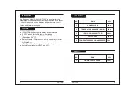
WIRING :
The probe and its corresponding wires should never be installed
in a conduit next to control or power supply lines. The electrical wiring
should be done as shown in the diagram. The power supply circuit should
be connected to a protection switch. The terminals admit wires of upto
2.5sq mm.
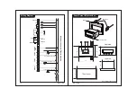
Fixing and dimensions of panel models :To fix the unit, slide the side lock
1
through the guides
2
as per the position shown in the figure. Move the side
lock in the direction of the arrow, it permits to move the fastener in the opposite
direction of the arrow.
3
Fit the screw in the side lock in direction of the arrow to
hold the controller in the panel.
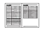
Installation
Controller
Controller should be installed in a place protected by vibration, water and
corrosive gasses and where ambient temperature does not exceed the values
specified in the technical data.
Probe
To give a correct reading, the probe must be installed in a place protected from
thermal influences, which may affect the temperature to be controlled.
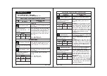
CAUTION
15
16
The information in this document is
subject
to change in order to improve
reliability , design or function without prior notice and does not represent
a
commitment on the part of the company. In no
event will the company be liable
for direct, indirect, special, incidental or consequential damage arising out of
the use or inability to use the product or documentation, even if advised of the
possibility of such damages. No part of this manual may be reproduced or
transmitted in any form or by any means without the prior written permission of
the company.
Notice
Disclaimer
Warranty
This product is warranted against defects in materials and workmanship for a
period of one year from the date of purchase. During the warranty period,
product determined by us to be defective in form or function will be repaired or,
at our option,
replaced at no charge. This warranty does not apply if the product
has been damaged by accident,
abuse, and misuse or as a result of service or
modification other than by the company. This warranty is in lieu of any other
warranty expressed or implied. In no event shall the company be held liable for
incidental or consequential damages, such as lost revenue or lost business
opportunity arising from the purchase of this product.
This manual & its contents remain the sole property of PVR Controls, India and
shall not be reproduced or distributed without authorization. Although great
care has been taken in the preparations of this document, the company or its
vendors in no event will be liable for direct, indirect, special, incidental or
consequential damage arising out of the use or inability to use the product or
documentation, even if advised of the possibility of such damages. No part of
this manual may be reproduced or transmitted in any form or by any means
without the prior written permission of the company. PVR Controls reserves the
right to make and changes or improvements without prior notice.
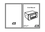
NC-110A
NC-110A


