background image

www.PyleUSA.com

www.PyleUSA.com

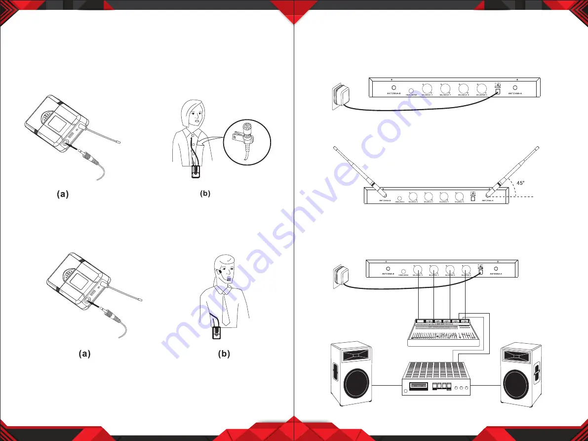
BODYPACK TRANSMITTER CONNECTION

1. Lavalier Microphone Connection:

 Connect the connector of supplied  


     lavalier microphone to the connecting jack of transmitter (shown as below)   
     Set the transmitter work state in wireless lavalier system (L).

2. Headset Microphone Connection:

 Connect the  connector of supplied  


     headset microphone to the connecting jack of transmitter (shown as below)  
     Set the transmitter work state in wireless headset system (H).

7

8

SYSTEM CONNECTION

1. Receiver Power Connection: 

Connect the DC connector of supplied AC/DC   

     adapter Into the DC power input of receiver. Plug the AC Input connecter    
     into an AC120/60Hz or AC220V/50Hz outlet. (Shown as below)

2. Antenna:

 Keep the position of antenna at a 45 angle from vertical.

    (Shown as below)

3. Audio Connection:

 Connect the corresponding output of receiver by  


     supplied 1/4w phone jack audio cable or your XLR cable to the Input of  


     power amplifier, mixer.

Summary of Contents for PDWM4350U

Page 1: ...UHF Wireless Microphone System Kit PDWM4350U PDWM4360U PDWM4350U PDWM4360U ...

Page 2: ...ver 2 Simultaneous Output Use Unbalanced 1 4 phone plug and balanced XLR output connectors may be used simultaneously to different external devices 3 Range UHF Series transmitters will work at a distance of up to 50 meters about 164ft from the receiver 4 Noise Squelch Squelch circuit analyzes signal strength and quality so that it can reduce the likelihood of noise burst due to environmental RF Ra...

Page 3: ...Antenna 9 XLR Balanced Output Jack Connect the audio cable from this jack to the input port of amplifier mixer 10 Volume Knob Adjust the volume output of receiver 11 1 4 Audio Output Jack Connect the audio cable from this jack to the Input port of amplifier mixer 12 Power Jack Connect the DC adapter to receiver 3 4 MICROPHONE TRANSMITTER FEATURES 1 Grille Protects the cartridge and help reducing t...

Page 4: ...requency channelect 7 Gain Adjusting Volume Adjust the transmitter audio input gain 8 State Setting Switch Set the using state of lavalier system L headset system H 9 Up Function Button Sets channel data 10 Down Function Button Sets channel data 5 6 TRANSMITTER BATTERY INSTALLATION 1 Battery Installation of Handheld Microphone Open the battery cover Insert the supplied batteries into battery jar i...

Page 5: ...cting jack of transmitter shown as below Set the transmitter work state in wireless headset system H 7 8 SYSTEM CONNECTION 1 Receiver Power Connection Connect the DC connector of supplied AC DC adapter Into the DC power input of receiver Plug the AC Input connecter into an AC120 60Hz or AC220V 50Hz outlet Shown as below 2 Antenna Keep the position of antenna at a 45 angle from vertical Shown as be...

Page 6: ...owing Receiver signal indicators A B lights glowing Red transmitter indicator is flashing Slide transmitter POWER ON OFF switch to ON position Make sure battery is inserted properly observing battery If the battery is inserted properly replace with fresh battery Slide transmitter MUTE ON switch to ON position Make sure AC adapter is securely plugged into electrical outlet and into DC input connect...

Page 7: ...in LESS THAN 100mA Modulation Type FM RF Output MORE THAN 10dBm Max Deviation 70KHz Spurious Emission MORE THAN 55dB Dimensions 238MM X 50MM X 50MM Power Requirements 1 5VAA battery X2 Nominal Current Drain LESS THAN 100mA Modulation Type FM RF Output MORE THAN 10dBm Max Deviation 70KHz Spurious Emission MORE THAN 55dB Dimensions 100MM X 65MM X 30MM PDWM4350U PDWM4360U ...

Reviews: