background image

2

INTRODUCTION

RESET FUNCTION

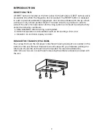
A RESET button is located on the front panel (to the left side of EJECT button) and is
accessible only when the magazine door is opened. The RESET button is recessed
in order to prevent accidental engagement, and can be activated with the tip of ball-
point pen or any similar pointed object. The reset circuitry is provided in order to
protect the unit's microprocessor and tracking system and should be activated only
under the following conditions:
 a. Initial installation after all wiring is completed;
 b. Abnormal operation is encountered such as not loading a Disc; and
 c. Indication on controller display is erratic.

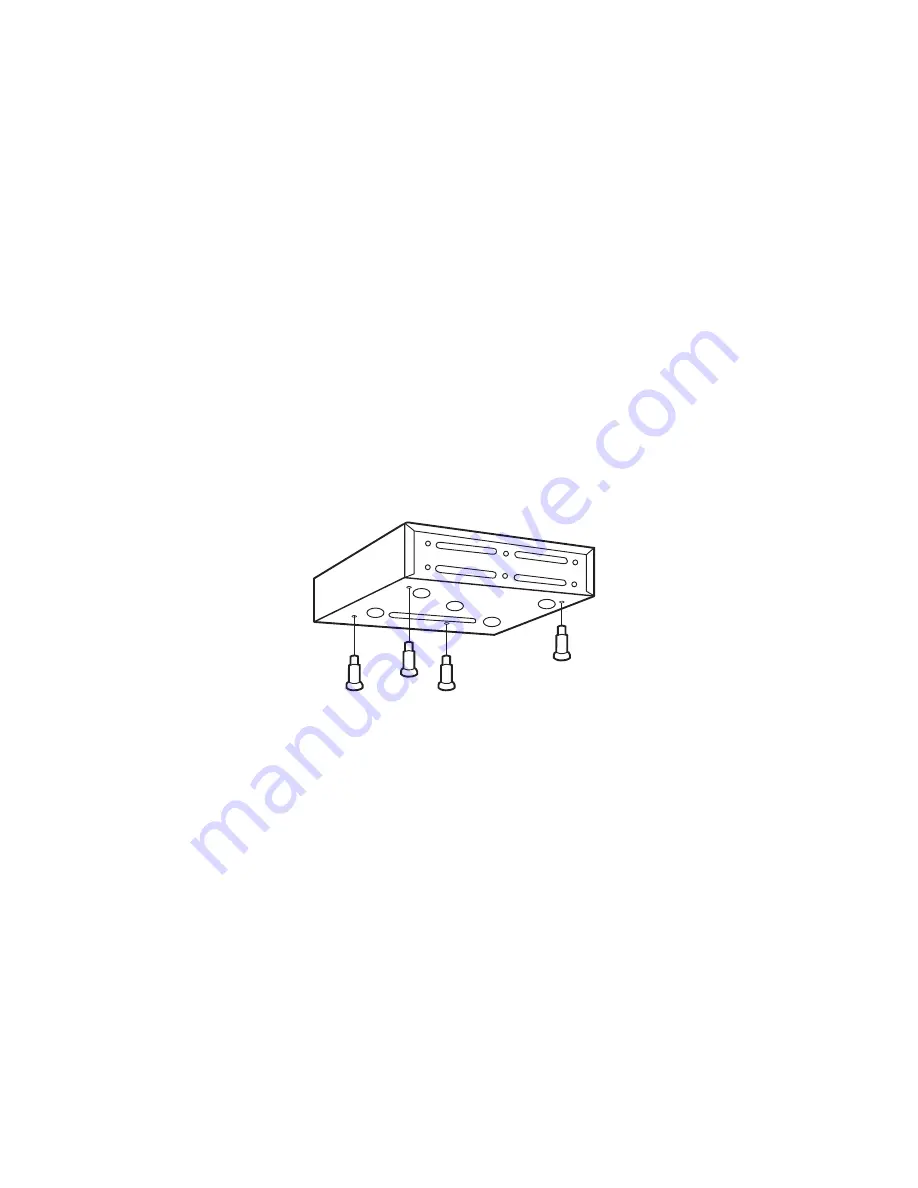
REMOVE THE TRANSPORT SCREWS

Four screw that lock the CD player's mechanism during transport are located on the
bottom of the unit. Remove these screws and keep with your literature package for
future use should the unit need to be transported for service/maintenance.
After removal, be sure to seal these holes using the adhesive stickers provided with
the unit.

Summary of Contents for DISC CD CHANGE

Page 1: ...INSTRUCTION MANUAL 6 DISC CD CHANGER PLCHD6 ...

Page 2: ...soft line free cloth Do not use sprays or cleaners designed for records Do not expose the Disc to direct sunlight Excessive heat will warp the Disc Do not leave a Disc unprotected Always store it in its case right away from sunlight Compact Discs may not always be recorded at the same volume level or with the same quality This may result in different volume levels between Disc and radio ENVIRONMEN...

Page 3: ...tracking system and should be activated only under the following conditions a Initial installation after all wiring is completed b Abnormal operation is encountered such as not loading a Disc and c Indication on controller display is erratic REMOVE THE TRANSPORT SCREWS Four screw that lock the CD player s mechanism during transport are located on the bottom of the unit Remove these screws and keep...

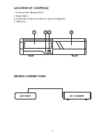
Page 4: ...3 LOCATION OF CONTROLS 1 Compact Disc Magazine Slot 2 Reset Button 3 Eject Button Press this button to eject the Magazine 4 Slide Door WIRING CONNECTIONS CAR RADIO CD CHANGER 1 2 3 4 ...

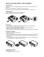
Page 5: ... to disassemble the magazine Take care not to drop the magazine or knock it against hard surfaces Store the pulled out magazine in a safe place Benzine thinner or other volatile chemicals may cause damages to the magazine Inserting the magazine 1 Slide the door open to the right side 2 Insert the magazine Make sure that the magazine toadied with Discs before inserting it into the player Be careful...

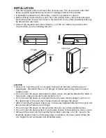
Page 6: ...there is not danger of passengers being injured case of sudden stops Do not mount the player near heater outlets where it might be affected by heat or near doors where rainwater might splash onto it Do not mount the player in a location that will receive direct sunlight such as on the dashboard or the rear shell Excess heat will damage the player When mounting the player make sure no wires are tra...

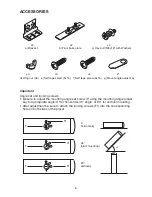
Page 7: ...mportant Angle set and locking screws Be sure to adjust the mounting angle set screw F using the mounting angle adjust key to appropriate angle Of for horizontal 45 angle or 90 for vertical mounting After adjustment be sure to attach the locking screws F1 into the corresponding hole on both sides of the player 6 45 o F1 F F1 F F1 F 0 horizontally 45 slant mounting 90 vertically ...

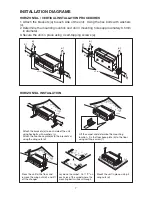
Page 8: ...r base plate b to the brackets a using the wing nuts d Lift the carpet and determine the mounting location Fix the floor base plate b to the floor using self tape screw f c e a a d c b b d d d d INSTALLATION DIAGRAMS HORIZONTAL VERTICAL INSTALLATION PROCEDURES 1 Attach the brackets a to each side of the unit Using the hex bolts with washers c 2 Determine the mounting location and drill 4 mounting ...

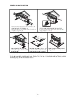
Page 9: ...arpet Cut 1 X on each area of the carpet where the mounting bolts will pass through Mount the unit in place using 4 wing nuts d Attach the brackets a to each side of the unit using hex bolts with washers c Attach the floor base plate b to the brackets a using the wing nuts d Lift the carpet and determine the mounting location Fix the floor base plate b to the floor using self tape screw f c e a a ...

Page 10: ...Ordinary room condition of temperature 68 5 4 F and relative humidity 65 DC 14 4 0 2V Audio Frequency range 20Hz 20KHz 1dB Dynamic range 90dB or more Distortion THO N 0 1 or less at 1KHz S N ratio 90dB or more at 1KHz Channel separation 70dB or more at 1KHz Audio output level 1 25V 0 05V 1KHz 0dB Wow Flutter Below the measuring unit SCRATCH 0 8 mm INTERRUPTION 0 8 mm BLACK DOT 0 8 mm FINGER PRINT ...

Page 11: ...on or the disc button Play Pause Button Play Pause 4 To pause all play functions of CD Changer Push the Pause button To return to play mode depress the Pause button again Track Selection Track up down and Track FF REW 5 10 These button are used to search for a disc or track quickly Press T Up or T Down button to search to the desired track or disc Disc and track information will be displayed on th...

Page 12: ...han 3 time of Focusing trial Error 8 CLV On is not operated to reach CLV constant speed Mode and Subq input is proven Error Error 9 TOC is not read after a certain time 15 sec passed Error 10 The temperature in the mechanism continues to rise for a certain times 5 sec so no more operation can be done Note When the system is turned off in the car power always goes back to the radio not back to the ...

Reviews: