background image


10

BATTERY INSTALLATION 

WARNING

: To avoid electric shock, disconnect the test leads 

from any source of voltage before removing the battery door. 

1. 

Disconnect the test leads from the meter. 

2. 

Open the battery door by loosening the screw using a Phillips 

head screwdriver. 

3.  Insert the battery into battery holder, observing the correct 

polarity. 

4. 

Put the battery door back in place. Secure with the screw. 

WARNING: 

To avoid electric shock, do not operate the meter 

until the battery door is in place and fastened securely. 

NOTE

: If your meter does not work properly, check the fuses and 

batteries to make sure that they are still good and that they are 

properly inserted. 


OPERATING INSTRUCTIONS 

WARNING

: Risk of electrocution. High-voltage circuits, both AC and 

DC, are very dangerous and should be measured with great care.


Summary of Contents for PDMT08

Page 1: ...1 OPERATING INSTRUTIONS DIGITAL MULTIMETER PDMT08 www pyleaudio com...

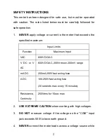
Page 2: ...Input Limits Function Maximum Input VAC 600V DC AC V DC or V AC 600V DC AC 200Vrms on 200mV range mA DC 200mA 250V fast acting fuse A DC 10A 250V fast acting fuse 30 seconds max every 15 minutes Resis...

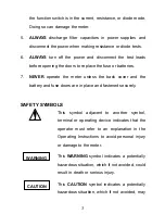
Page 3: ...the meter unless the back cover and the battery and fuse doors are in place and fastened securely SAFETY SYMBOLS This symbol adjacent to another symbol terminal or operating device indicates that the...

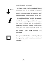
Page 4: ...ase 500 VAC or VDC This symbol adjacent to one or more terminals identifies them as being associated with ranges that may in normal use be subjected to particularly hazardous voltages For maximum safe...

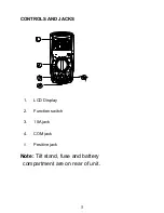
Page 5: ...5 CONTROLS AND JACKS 1 LCD Display 2 Function switch 3 10A jack 4 COM jack 5 Positive jack Note Tilt stand fuse and battery compartment are on rear of unit...

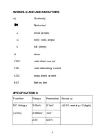
Page 6: ...mps m milli volts amps k kilo ohms ohms VDC volts direct current VAC volts alternating current ADC amps direct current BAT Battery test SPECIFICATIONS Function Range Resolution Accuracy 200mV 0 1mV 20...

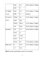
Page 7: ...A 20mA 10 A 1 0 reading 2 digits 200mA 100 A 1 2 reading 2 digits DC Current A DC 10A 10mA 2 0 reading 2 digits 200 0 1 2000 1 20k 0 01k 200k 0 1k 0 8 reading 2 digits Resistance 2000k 1k 1 0 reading...

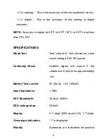
Page 8: ...ICATIONS Diode Test Test current of 1mA maximum open circuit voltage 2 8V DC typical Continuity Check Audible signal will sound if the resistance is less than approximately 30 Battery Test current 9V...

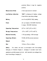
Page 9: ...50V fast blow Operating Temperature 32 o F to 122 o F 0 o C to 50 o C Storage Temperature 4 o F to 140 o F 20 o C to 60 o C Relative Humidity 70 operating 80 storage Operating Altitude 7000ft 2000 met...

Page 10: ...lder observing the correct polarity 4 Put the battery door back in place Secure with the screw WARNING To avoid electric shock do not operate the meter until the battery door is in place and fastened...

Page 11: ...ng This is normal and is caused by the high input sensitivity The reading will stabilize and give a proper measurement when connected to a circuit DC VOLTAGE MEASUREMENTS CAUTION Do not measure DC vol...

Page 12: ...ue AC VOLTAGE MEASUREMENTS WARNING Risk of Electrocution The probe tips may not be long enough to contact the live parts inside some 240V outlets for appliances because the contacts are recessed deep...

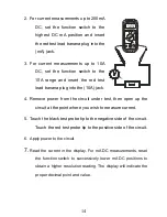
Page 13: ...to the positive side of the circuit 4 Read the voltage in the display Reset the function switch to successively lower V AC positions to obtain a higher resolution reading The display will indicate the...

Page 14: ...4 Remove power from the circuit under test then open up the circuit at the point where you wish to measure current 5 Touch the black test probe tip to the negative side of the circuit Touch the red te...

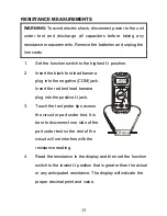
Page 15: ...lug into the negative COM jack Insert the red test lead banana plug into the positive jack 3 Touch the test probe tips across the circuit or part under test It is best to disconnect one side of the pa...

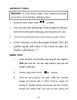
Page 16: ...to check 4 If the resistance is less than approximately 30 the audible signal will sound If the circuit is open the display will indicate 1 DIODE TEST 1 Insert the black test lead banana plug into th...

Page 17: ...he positive V jack 2 Select the 1 5V or 9V BAT position using the function select switch 3 Connect the red test lead to the positive side of the 1 5V or 9V battery and the black test lead to the negat...

Page 18: ...e the Battery Installation section of this manual 3 Dispose of the old batteries properly WARNING To avoid electric shock do not operate your meter until the battery door is in place and fastened secu...

Page 19: ...ize and value 0 5A 250V fast blow for the 200mA range 10A 250V fast blow for the 10A range 6 Put the fuse door back in place Insert the screw and tighten it securely WARNING To avoid electric shock do...

Reviews: