www.PyleUSA.com
7
C. MOUNTING
1. Place the crossover at the desired location and use it as a template to
determine the exact position of the mounting holes. Mark the mounting
holes with a pen.
2. Use a center punch to ensure drilling the exact position for the screws.
Drill four (4) 1/8 pilot holes.
DO NOT BEGIN DRILLING UNTIL YOU HAVE
PUT THE CROSSOVER ASIDE. USING THE CROSSOVER AS DRILLING
GUIDE MAY CAUSE IRREPAPABLE DAMAGE TO THE COROSSOVER.
3. Mount the unit with the Philips head sheet metal screws and steel washers
provided.
D. WIRING
1. Run the various wires according to your wiring layout, avoiding sharp edges
and door jams.
2. Electrical tape or grommets should be used to protect the wires when they
are routed through bare metal holes.
Note:
The battery ground should remain
DISCONNECTED
at all stages of installation.
E. CONNECTIONS
1.
Connect the crossover to the Source Unit
Connect the outputs of the source unit to the inputs of the crossover (either
via the low impedance input or the high impedance input).
2.
Connect the crossover to the Amplifiers
Connect the high-pass and low-pass outputs of the crossover to the inputs
of their respective amplifiers.
3.
Connect the Amplifiers to the Speakers
Connect the various amplifiers to their speakers following the amplifier's
manual and specifications.
4.
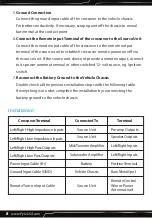
Connect the crossover to the Battery
Connect the power input cable to the positive terminal of the battery.
Add circuit breaker to any power wire that runs through firewall or sheet
metal to protect the battery, the vehicle, and more importantly, you.
Summary of Contents for PLXR2B
Page 1: ...2 Way Electronic Crossover Network Independent High Pass Low Pass Output Level Controls ...
Page 5: ...www PyleUSA com 5 SYSTEM DIAGRAM Remote Turn On Lead from Head Unit Battery Positive B A B ...
Page 13: ...www PyleUSA com 13 ...
Page 14: ...Questions Issues We are here to help Phone 1 718 535 1800 Email support pyleusa com ...


