background image

www.PyleUSA.com

3

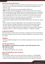
REMOTE TURN-ON CONNECTION

The amplifier is turned on by ap12V to the remote turn-on terminal (REM). 
The wire lead to this terminal should be connected to the "Auto-Antenna" lead 
from the vehicle/or boat stereo resources which will provide the +12V only when 
the stereo resources is turned on . If the car stereo does not provide an "Auto-An-
tenna" lead, the remote turn-on lead may be wired to an "Accessory" or "Radio" 
terminal in the vehicle’s/or boat’s fuse block. This will turn the amplifier on and off 
with the ignition key, regardless of whether the stereo resources is on or off. 
The remote turn-on lead does not carry large currents. So #16 gauge wire may be 
used for this application.

SPEAKER CONNECTIONS

Depending on the type and number of speakers used with the amplifier wire them 
to the speaker terminals as per the appropriate wiring diagram. For most applications 
#18 gauge wire should be used for the speaker leads but in no case thinner than 
#16 gauge. For leads is excess of 10 feet #12 gauge is recommended. When wiring 
the speakers, pay careful attention to the polarity of the terminals on the speakers 
and make certain they correspond to the polarity of the corresponding terminals 
on the amplifier. Do not ground any speaker leads to the chassis of the vehicle/or 
boat.

OPERATION

After the amplifier has been installed and all connections have been made carefully 
and securely, turn the radio on so that the amplifier is switched on automatically. 
After a short power-on period, the amplifier reaches its full performance. Now turn 
up the volume slowly using the volume control of the radio. If there is no sound or 
only a distorted replay, switch off the radio immediately - the amplifier will also 
switch off automatically - and check if all connections have been made correctly.

GND (-) = GROUND CONNECTION

Connect the GND terminal to the chassis ground of your vehicle/or boat and
take care of best electric and mechanic contact. In doing so, drill a hole into the 
vehicle/or boat chassis near the amplifier then remove color, dirt or any other 
substance from the ground point. Thereafter fasten the cable end with added ring 
terminal by using a screw. Ensure that the ground connection is as short as possible 
and that the cable diameter is sufficient (min 4mm). Route the ground cables from 
the radio and all other equipment parts, like equalizer, active crossover network or 
other amplifiers, to the same ground point.

Summary of Contents for Power sports PLUTV42CH

Page 1: ...PLUTV42CH 800W Waterproof Marine Speakers 2 Ch Rated Amplifier PowerSport Amp for ATV UTV 4x4 Jeep Wired RCA AUX and MP3 Audio Input Cable for Boat Stereo Speaker Other Watercraft ...

Page 2: ... battery as its optimum performance depends on a normal battery supply voltage For safety reasons keep the volume of your audio system moderate so that you can still hear normal traffic sounds in a reasonable distance WIRING INSTRUCTIONS POWER CONNECTION The battery terminal BATT must be connected directly to the positive terminal of the vehicle battery to provide an adequate voltage source and mini...

Page 3: ...on the speakers and make certain they correspond to the polarity of the corresponding terminals on the amplifier Do not ground any speaker leads to the chassis of the vehicle or boat OPERATION After the amplifier has been installed and all connections have been made carefully and securely turn the radio on so that the amplifier is switched on automatically After a short power on period the amplifi...

Page 4: ...ery The lead cable s diameter should be at least 4 mm for a length of 3 m and 6 mm for a length of 6 m REM ON OFF REMOTE CONTROL Connect the REM terminal to the automatic antenna connector of your vehicle or boat radio Now when turning on and off your vehicle or boat radio the amplifier automatically switches ON and OFF A cable diameter of 0 5mm2 is sufficient SPEAKERS CONNECTIONS POWER CONNECTION LE...

Page 5: ...lose as possible to the car battery During a full power operation Maximum current will run through the system Therefore make sure that the leads to be connected to the 12V and GND terminals of the unit respectively must be larger than 18 Gauge AWG 18 proper Bridged operation If only mono signal is available a Y adapter is required FUSE REPLACEMENT If the fuse blows check the power connection and r...

Page 6: ... signal speaker and power cables separately with enough distance from one another and also from each other car cable If not possible you can lay the circuit and ground cable together with the serial cables Audio and speaker cable should be as far away from these as possible The REM cable to the automatic antenna output of the radio can be laid together with the signal cables Avoid ground loops by ...

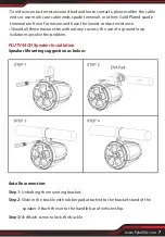
Page 7: ...t contact resistance Should all these meaures be without any success the use of a ground loop isolator may solve the problem PLUTV44CH Speaker Installation Speaker Mounting suggestion as below Auto Reconnection Step 1 Unbolting the mounting bracket Step 2 Slide in the buckle with rubber pad attached to the bracket stand of the speaker Attach the set to the handle bar of vehicle ship Step 3 4 Attac...

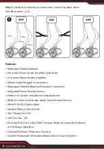
Page 8: ...on Waterproof Rated Weather Resistant Connectors Integrated Power Wiring Harness Perfect for Custom Installations Applications Ability to Connect Stream Audio from External Devices Wired RCA AUX Audio Input Speaker Wiring Connectivity Anti Thump Turn On Soft Turn On Off Pre Amp RCA Out to Any OEM Factory Made Universal Mono Block or Full Range Amplifier Overload Power Protection Circuitry Used for ...

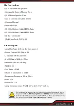
Page 9: ...ponent Power Output 800 Watt MAX 2 x 45 Watts RMS 4 Ohm 2 x 150 Watts MAX 4 Ohm Marine Grade IP 65 Rating T H D 0 1 S N Ratio 93dB Channel Separation 50dB Frequency Response 20Hz 20kHz Fuse 15A Power DC 12V Amp Dimensions L x W x H 5 3 x 3 6 x 1 97 inches This products can expose you to a chemical or group of checmicals which may include Di 2 ethylhexyl phthalate DEHP which is known in the state o...

Page 10: ...Questions Issues We are here to help Phone 1 718 535 1800 Email support pyleusa com ...

Reviews: