SVS-VISTEK
Feature-Set
47
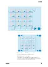
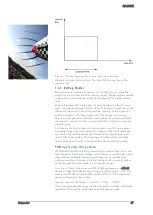
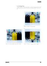
Figure 1: All pixel lines are sensitive to light the same time
All pixels are open the same time. You might flash at any time within
exposure time.
7.1.3
Rolling Shutter
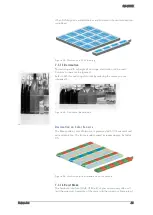
Rolling shutter is a method of reading out a CMOS sensor, where the
whole scene is scanned line after line very rapidly. Rolling shutter cameras
in general are more sensitive in their light response than global shutter
ones.
Despite the speed of scanning one line after the other („rolling“) is very
high, it is important to note that the instant of imaging a single line will be
different to the point of time of the next line imaging. As this works out
without any effect in the final image with still sceneries, with moving
objects you get geometric distortions (see example of rotating propeller),
showing fast moving structures in an predictable, in the first moment yet
surprising way.
As it takes some time to read out a whole sensor (and the whole sensor
has always to be read out!) you need to make sure that light conditions
are stable while reading the sensor. This restriction applies especially to
using PWM driven lights or flash lighting with rolling shutter. Unstable
light conditions will result in a horizontal line structured pattern noise.
PWM lights with rolling shutter
PWM (Pulse Width Modulated) powered light or dimmed light is run at a
fixed frequency. Experience teaches us this frequency might be less stable
than expected. Unstable frequency might show up as unstable light,
creating noise/line structures in the final rolling shutter image (in global
shutter images the whole image is just more/less bright)
As a rule of thumb, make sure your PWM lighting frequency is at least
double or triple the bitdepth of your image (e.g. 8bit image = 256, this
means your PWM has to be switched at least 256*2=512 times) while
exposing. If exposure time is 5ms,
required minimum PWM freq = 5ms/512 ~ 10µs ~ 100kHz
If you have the possibility to use a strobe controller or dimmer with linear
regulation, this might be preferrable on short exposure times.
Summary of Contents for EXO Series
Page 21: ...SVS VISTEK Connectors 21 ...
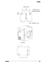
Page 26: ...SVS VISTEK Dimensions 26 Side Right Top ...
Page 27: ...SVS VISTEK Dimensions 27 Bottom Back ...
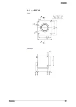
Page 28: ...SVS VISTEK Dimensions 28 Cross Section 6 2 exo250 CL exo252 CL front side Left ...
Page 29: ...SVS VISTEK Dimensions 29 ...
Page 30: ...SVS VISTEK Dimensions 30 Side Right Top ...
Page 31: ...SVS VISTEK Dimensions 31 Bottom Back Cross Section ...
Page 32: ...SVS VISTEK Dimensions 32 6 3 exo267 CL exo304 CL ...
Page 33: ...SVS VISTEK Dimensions 33 ...
Page 34: ...SVS VISTEK Dimensions 34 ...
Page 35: ...SVS VISTEK Dimensions 35 6 4 exo4000 CL front side Left ...
Page 36: ...SVS VISTEK Dimensions 36 Side Right Top ...
Page 37: ...SVS VISTEK Dimensions 37 Bottom Back ...
Page 38: ...SVS VISTEK Dimensions 38 Cross Section ...
Page 39: ...SVS VISTEK Dimensions 39 6 5 exo5000 U3 front side Left ...
Page 40: ...SVS VISTEK Dimensions 40 Side Right Top ...
Page 41: ...SVS VISTEK Dimensions 41 Bottom Back Cross Section ...
Page 65: ...SVS VISTEK Feature Set 65 ...
Page 71: ...SVS VISTEK Feature Set 71 Figure 42 I O Lines with open end indicate physical in and outputs ...
Page 124: ...SVS VISTEK Troubleshooting 124 Space for further descriptions screenshots and log files ...


