PTC System Controls and Diagnostics
CP15 User Manual CP15_UM_221017 Page 22 of 33
12
Setup and Calibration
12.1 Gain setting
The photomultiplier tube in a scintillation detector provides the large gain that converts the faint
light from a single detection event into a readily measurable pulse of electrons. The amount of
gain is determined by the high voltage applied to the photomultiplier in a non-linear fashion.
Although it is possible to see low energy detection events by applying sufficient voltage, there
are limitations:
- the tube will have a maximum allowed voltage
- as the voltage is increased, random “dark current” pulses released spontaneously become more
frequent and larger, leading to unwanted background.
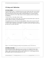
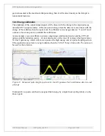
The adjustable gain of the CP15 allows the photomultiplier voltage to be set at a safe level with
acceptable background signal. The pulse height of the signals of interest can then be set into a
convenient range by adjusting the gain trimpot. A clockwise rotation of the trimpot increases the
gain between zero and the maximum.
Figure 11 CP15AF increasing gain setting, showing saturation onset in the final view
12.2 Offset correction
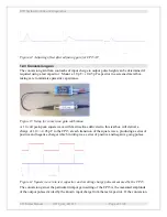
The offset trimpot should be adjusted as necessary to remove any residual DC offset on the
output. This can be observed by looking at the output signal on an oscilloscope. The offset is
slightly coupled to the gain setting, more noticeably for the CP15AF. After setting the desired
gain, adjust the offset to return the baseline to zero volts.


