PTC System Controls and Diagnostics
CP15 User Manual CP15_UM_221017 Page 27 of 33
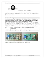
View external looking on connector
Connector body and pin 3 connects directly to CP15 analog ground. Pin 2 connects to analog
ground via ferrite bead.
13.3 Internal settings
We do not recommend that you open the CP15 case unless specifically instructed to do so by
your supplier or Pyramid Technical Consultants, Inc. It is possible to damage the circuits or
degrade noise performance if correct handling precautions are not employed.
The following information is provided for reference. To open the case, remove two M2.5 hex
cross head screws from each end of the case. The top of the case can then be removed to reveal
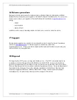
the circuit. A 2 mm jumper near the output sets the relationship between the input signal polarity
and the output signal polarity.
INV
Output voltage is the opposite polarity to the input charge (default
configuration)
NONINV
Output voltage is the same polarity as the input charge
Figure 17. Location of internal jumpers; left CP15AF, right CP15AL.
4: +12 V
1: -12 V
3: AGnd
2: AGnd
(LR)


