PSI System Controls and Diagnostics
I128r5 User Manual
I128r5_UM_190923 Page 26 of 123
8.3 Connection to signal source
Example setup
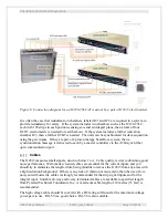
Figure 7 shows an example installation to read out an ionization chamber. The position-sensing
ionization chamber includes 64 by 64 strip electrodes for reading out the position of a high-
energy particle beam plus an integral plane (also known as a dose plane) electrode for measuring
the total current. The x-axis strips are shown connected to channels 1-64 and the y-axis strips to
channels 65-128. The integral plane is connected to the channel 0 (“high current channel”,
HCC) input.
When thinking about the current measurement range you will require, consider the gain of the
ionization chamber, the size of the beam and the dimensions of readout electrodes. Gain is
typically in the range 30 to 200 for high energy protons which pass through a parallel plate
ionization chamber at normal incidence, depending on electrode spacing, fill gas pressure and
ion species and energy. Thus a beam current of 1 nA for example and a chamber gain of 100
would produce a measureable total signal of 100 nA. A strip readout electrode where the beam
covered around 10 strips full width would give individual strip currents of 20 to 30 % of this
total, thus 20 to 30 nA.
High voltage is delivered to the high voltage electrodes and sampled by an independent loopback
cable. Environmental sensors, such as provided in the IC128-25LC ionization chamber are
connected to the sensor signals input of the I128r5. There are inputs for temperature, pressure
and humidity. The I128r5 can perform real time correction for temperature and pressure and tag
the measured signals with these values.
The I128r5 delivers data and receives commands from a host computer system over Ethernet. In
its turn the I128 can control slave devices such as the M10 general purpose I/O unit. This can be
used to form a control loop, where some remote device is adjusted in response to the signals
measured by the I128r5.
A trigger input to the gate connector allows measurements to be synchronized to an external
event such as a “beam present” signal. Hardware interlock signals generated by the I128r5
(potential-free contacts or 24 V logic) are routed directly to one or more beam abort systems.
The decisions to open these interlocks are made by the I128r5, for example by comparing beam
position, shape or current to target values, or as a result of internal errors.
The I128r5 can generate an output “monitor Q unit” pulse each time it measures a defined
increment of charge, which may be used to drive an independent counter or sounder.
Other fiber optic control lines are provided for control and monitoring an accelerator for use in
the proton therapy application. Relay outputs allow the I128r5 to open interlock loops to inhibit
accelerator beam output in fault conditions.

