PSI System Controls and Diagnostics
I128r5 User Manual
I128r5_UM_190923 Page 52 of 123
10.4.4.1
Measuring sub-tab
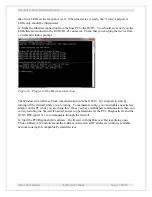
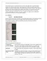
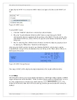
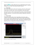
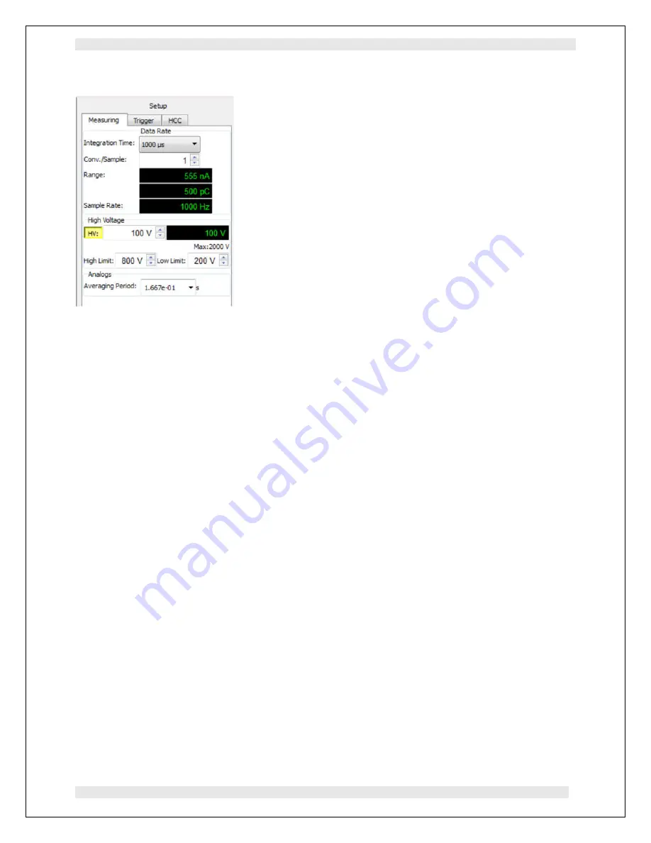
Figure 30. Setup - Measuring sub-tab
The Measuring sub-tab is where you select integration time to be used by the ADAS
electrometer chip. The drop down control provides times from 55 µsec to 1000 µsec. The same
time is used for the HCC. If the HCC is working in I-V converter mode, then it determines the
number of ADC readings that are averaged per charge reading. If the HCC is operating in gated
integrator mode (future option), the time used is the selected integration time minus the times
defined to reset the integrator. You can only use the gated integrator mode when the selected
integration time exceeds the sum of the times that form the reset sequence (setup, reset and settle
times), which is typically about 50 µsec.
The time to generate each reading of 128 +1 signals that you see is the product of the integration
time and the conversions per sample that are averaged by the on-board FPGA. The maximum
Conv./Sample value is 255, so the longest accumulation for a single reading is 1000 µsec x 255 =
0.255 seconds, or a data rate of 4 Hz. At the other extreme, the highest data rate of 18.2 kHz is
obtained using 55 µsec x 1 = 55 µsec. As you alter these values, the read backs below show the
resulting full scale current, full scale charge and sample rate, based on the configuration of the
ADAS electrometer chip that produced the desired settings.
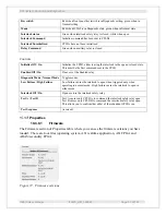
The HV controls allow you to set the voltage, enable or disable the supply, and define alarm
limits for the monitored high voltage. If you have a negative HV module installed, then you
must enter negative numbers. The maximum voltage available from the installed HV module is
displayed, as determined by jumper settings in the I128.
10.4.4.2
Trigger sub-tab
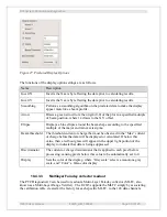
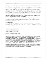
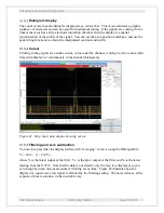
The Trigger sub-tab is where you set up the trigger conditions. There are various trigger modes
available. The most useful are the basic Internal triggering without buffering, which will always
show you a real time response on the PTC DiagnosticG2 display. For more complex triggering
requirements, the Custom trigger controls allow you to define in detail the conditions for starting,
stopping and pausing acquisitions.


