PSI System Controls and Diagnostics
I128r5 User Manual
I128r5_UM_190923 Page 68 of 123
12
High Voltage Supplies
12.1 Setting the High Voltage Supplies
The I128r5 is available with a one-watt high voltage supply suitable for biasing ionization
chambers. The voltage range can be specified at time of purchase from 200, 500, 1000 and
2000V with either polarity. +2000 V is typical for transmission ionization chambers. The A61
processor reads internal jumpers on JB2 to detect the supply rating. Note that the supplies are
not intended to deliver output voltage less than about 10% of their maximum rating.
The front panel HV on LED illuminates when the high voltage output is enabled. The set value
can be adjusted at any time via software.
The outputs of the high voltage modules are filtered by an RC filter to reduce ripple and noise.
The filter time constant is reduced for lower voltage HV supplies, to avoid excessive voltage
drop at large current drains. You can see the actual output voltage because readback is taken
from a voltage divider after the filter, directly on the HV output. The voltage divider places a
fixed 20 Mohm load on the supply.
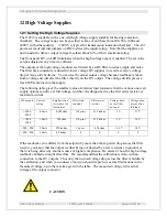
The following table gives the smallest value of external load resistance that the various one watt
supply options can drive at full voltage, and the volts dropped across the filer series resistor at
maximum current.
HV module Current
rating
Smallest load
resistance for
full output
Filter time
constant
Filter series
resistor
Voltage drop
across filter
no load
Voltage drop
across filter
full load
+2000,
-2000
0.5 mA
4.9 Mohm
110 µsec
33.2 kohm
3 V
17 V
+1000,
-1000
1.0 mA
1 Mohm
110 µsec
33.2 kohm
2 V
34 V
+500, -500
2.0 mA
220 kohm
16 µsec
4.7 kohm
< 0.1 V
10 V
+200, -200
5.0 mA
40 kohm
0
0
0
0
If the readback value differs from the setpoint by more than the expected drop across the filter
resistor, you know that the output is either being overloaded by a low resistance to ground, or
that it is being driven by another source of higher compliance. Be aware of how the high voltage
readback calibration might affect this. We recommend that the calibration is done with no
connection to the HV outputs. Thus only the no-load voltage drop across the filter is hidden by
the calibration, and when you connect a load you should expect to see small reductions in the
measured voltage, up to the maxima given in the table. The measured voltage is the actual
voltage at the output connector.
CAUTION

