Rins 181 Issue7
Page 3
CONTENTS
1.
INTRODUCTION
5
2.
SAFETY
5
3.
ACCESS
LEVELS
5
3.1
Limited
User
5
3.2
Master
User
5
3.3
Engineer
5
4.
FUNCTIONAL
DESCRIPTION
5
4.1
Operating
Modes
5
4.2
Entry
/
Exit
Mode
6
5.
ZONES
6
5.1
Engineer
Programmable
Zones
6
6.
DIAL OUT REPORTING
6
7.
FUNCTIONS
7
8.
INSTALLATION
AND
WIRING
11
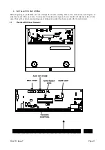
8.1
Plan
View
With
Cover
Removed
11
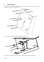
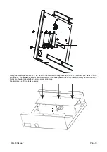
9.
PANEL
ASSEMBLY
11
10.
POWER
CONNECTIONS
14
10.1
Connections
14
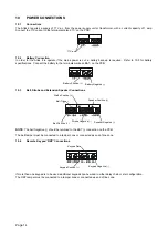
10.2
Battery
Connections
14
10.3
Bell, Strobe and Extension Speaker
Connections
14
10.4
Remote
Keypad
'RKP'
Connections
14
10.5
Battery
Capacity
15
10.6
End
Of
Line
Resistor
15
10.6.1
Atlas 8 End Of Line Resistor Wiring Diagram
16
10.6.2
Atlas 8 Double Pole Zone Wiring Diagram
16
10.7
Telephone
Connections
16
10.8
Powering
Up
The
panel
16
10.9
Atlas
End
of
Line
Wiring
Diagram
17
10.10
Atlas
Double
Pole
Wiring
Diagram
18
11.
PROGRAMMING
19
11.1
Factory
Defaults
19
11.2
Entering
Engineer
Mode
19
11.3
Setting
Volume
Control
19
11.4
Resetting The Non-Volatile Memory (NVM) to Factory Settings
19
11.5
Setting The Panel When Mains Fails
20
11.6
Programming
Set
Modes
20
11.7
Setting
The
Alarm
Bell
Time 20
11.8
Setting
Entry
Time
20
11.9
Setting
Exit
Time
20
11.10
Changing
The
Engineer
Code
21
11.11
Programming
Options
21
11.11.1
Programmable
Output
1
21
11.11.2
Programmable
Output
2
21
11.11.3
System
Option
1
22
11.11.4
System
Option
2
22
11.11.5
System
Option
3
22
11.11.6
System
Option
4
22
11.11.7
Programmable
Re-sets
23
11.11.8 Central Monitoring Station
Telephone
Number 23
11.11.9
Second
Telephone
Number 23
11.11.10
Customer
Account
Code
1
23
11.11.11
Downloading
Access
Code 23
Summary of Contents for BUMBT!8
Page 34: ...Page 34 ...
Page 35: ...Rins 181 Issue7 Page 35 ...


