background image

CAUTION!

RISK OF ELECTRIC SHOCK

DO NOT OPEN

TO REDUCE THE RISK OF ELECTRIC SHOCK DO NOT REMOVE COVER (OR BACK) 

NO USER-REMOVEABLE PARTS INSIDE

REFER SERVICING TO QUALIFIED PERSONNEL

This  symbol  indicates  that  there  are  important  operating  and 
maintenance instructions in the literature accompanying this unit. 

This symbol indicates that dangerous voltage constituting a risk of 
electric shock is present within this unit. 

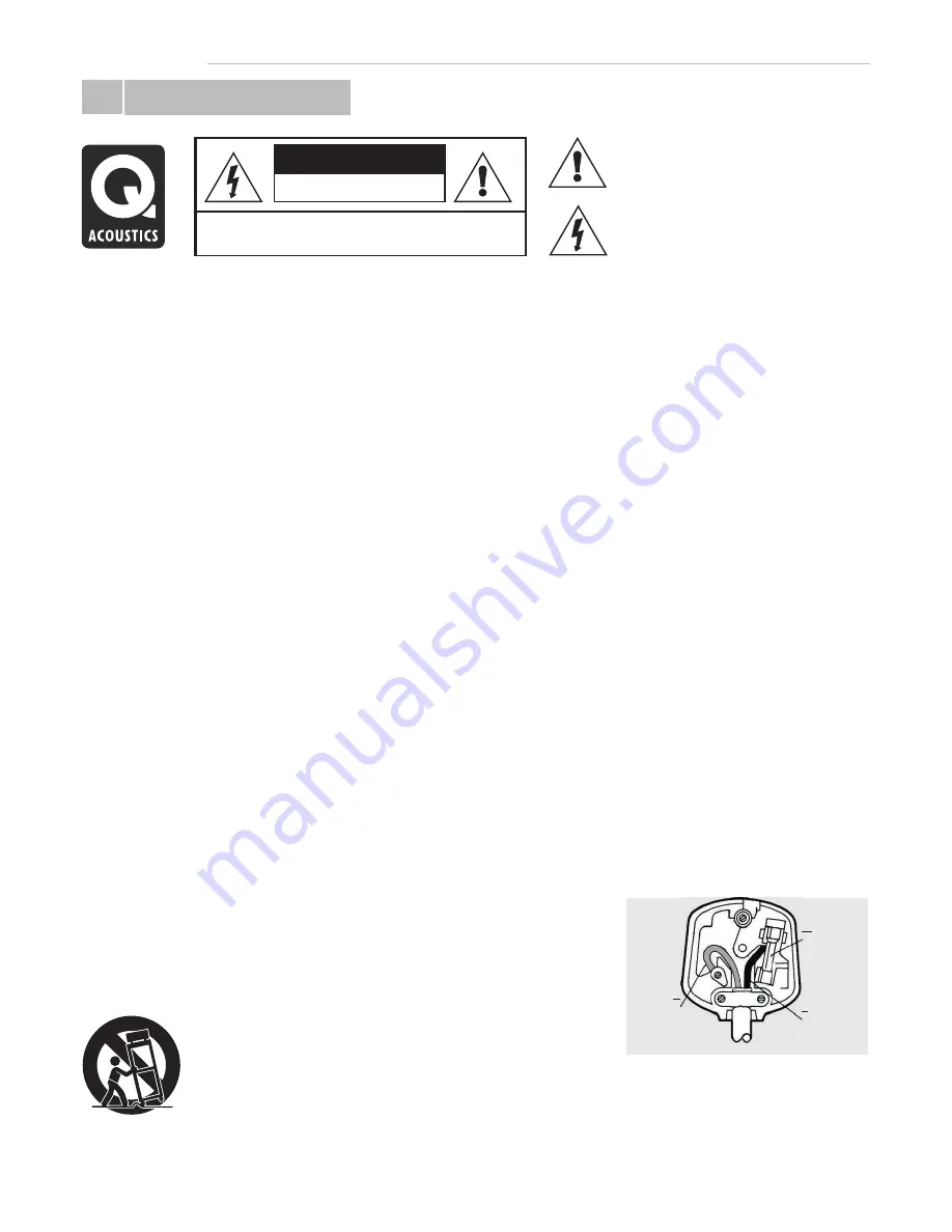
5A FUSE

BS 1362

BROWN

(Live)

BLUE

(Neutral)

Important Information- Please Read Carefully

3A FUSE

BS 1362

BROWN

(Live)

BLUE

(Neutral)

Safety

Ü

Quick Start Guide

Page 2

When  a  cart  is  used,  use  caution  when 

Read these instructions. 

m o v i n g   t h e   c a r t /   a p p a r a t u s  

Keep these instructions. 

combination  to  avoid  injury  from  tip-

Heed all warnings. 

over.

Follow all instructions. 

Unplug this apparatus during lightning 

storms or when unused for long periods 

Do not use this apparatus near water. 

of time.

Important notice to UK users

Clean only with dry cloth. 

The appliance cord is terminated with a 

Refer  all  servicing  to  qualified  service 

UK approved mains plug fitted with a 3A 

Do not block any ventilation openings. 

personnel.  Servicing  is  required  when 

fuse. If 

I n s t a l l   i n   a c c o r d a n c e   w i t h   t h e  

the apparatus has been damaged in any 

manufacturer's instructions.

way, such as power supply cord or plug is 
damaged,  liquid  has  been  spilled  or 

Do not install near any heat sources such 

objects  have  fallen  into  the  apparatus, 

as  radiators,  heat  registers,  stoves,  fire 

the apparatus has been exposed to rain 

places etc.

or moisture, does not operate normally, 
or has been dropped.

Do not defeat the safety purpose of the 

Warning:

  To  reduce  the  risk  of  fire  or 

polarized  or  grounding  type  plug.  A 

electrical  shock,  do  not  expose  this 

polarized plug has two blades with one 

product to rain or moisture. The product 

wider than the other. A grounding type 

must  not  be  exposed  to  dripping  and 

plug  has  two  blades  and  a  third 

splashing  and  no  object  filled  with 

grounding prong. The wider blade or the 

liquids  such as a vase of flowers  should 

third prong are provided for your safety. 

be placed on the product.

If the provided plug does not fit into your 
outlet,  consult  an  electrician  for 
replacement of the obsolete outlet.

No naked flame sources  such as candles  
should be placed on the product.

Protect  the  power  cord  from  being 
walked  on  or  pinched,  particularly  at 

Warning:

  The  mains  power  switch  for 

plugs, convenience receptacles, and the 

the power supply unit is the device used 

point  where  they  exit  from  the 

to  disconnect  the  unit  from  the  mains 

apparatus. 

supply.  This  switch  is  located  on  the 
power supply unit. To permit free access 
to  this  switch,  the  apparatus  must  be 

Use only attachments/accessories

located  in  an  open  area  without  any 

specified by the manufacturer. Use only

obstructions,  and  the  switch  must  be 

with a cart, stand, tripod, bracket, or

freely operable.

table specified by the manufacturer, or
sold with the apparatus.

Caution:  Changes  or  modifications  not 
expressly approved by the manufacturer 
could  void  the  user's  authority  to 
operate this device.

Third  parties:  In  the  unlikely  event  that 
you pass this product on to a third party, 
include  these  operating  instructions 
with the product.

the fuse needs to be replaced, an 

ASTA or BSI approved BS1362 fuse rated 
at  3A  must  be  used.  If  you  need  to 
change the mains plug, remove the fuse 
and  dispose  of  this  plug  safely 
immediately  after  cutting  it  from  the 
cord.

Connecting a mains plug


The wires in the mains lead are coloured 
in  accordance  with  the  code:    Blue: 
NEUTRAL;     Brown: LIVE: 

As these colours may not correspond to 
the  coloured  markings  identifying  the 
terminals  in  your  plug,  proceed  as 
follows: 

The BLUE wire must be connected to the 
terminal  marked  with  the  letter  N  or 
coloured  BLUE  or  BLACK.  The  BROWN 
wire must be connected to the terminal 
marked  with  the  letter  L  or  coloured 
BROWN or RED. 

Summary of Contents for Q-TV2

Page 1: ...User Manual for 30 42 Screens Q TV2...

Page 2: ...ns and replacements 14 Setup 14 Lip Sync 06 Fixing Rails 07 Fitting Q TV2 08 Adjusting Q TV2 arms Q Acoustics Q TV2 is the latest innovative audio solution in the Q AV range Using the latest slim line...

Page 3: ...ther A grounding type must not be exposed to dripping and plug has two blades and a third splashing and no object filled with grounding prong The wider blade or the liquids such as a vase of flowers s...

Page 4: ...solution to HD Sound Q TV 2 requires only one audio connection between the TV and itself to significantly improve the acoustic performance of your flat screen TV Q TV2 also acts as a music system when...

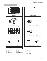
Page 5: ...xing Kit Fixing Kit Contents 1 x RCA PHONO Cable 4 x Rail Spacer Short 4 x Rail Spacer Long 2 x Security Pin 1 x Remote Control 2x AAA Batteries 1 x Small Allen Key 4 x M4 x 20mm 4 x M4 x 50mm 4 x M4...

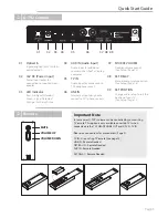
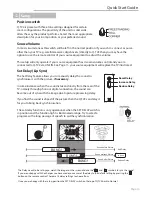
Page 6: ...Green Signal Detected Orange Set Delay Active 01 02 04 03 05 06 07 08 SET DELAY 09 SET POSITION Manual audio synchronisation See Setup Page 14 Change audio setup to suit the position of your TV See Se...

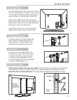
Page 7: ...rear of your TV using the screens fixing points Located on the rear of your screen will be threaded fixing points designed for wall mounting Use these fixings to attach Q TV2 Every screen is different...

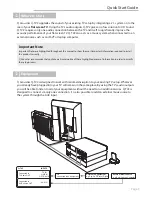
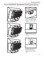
Page 8: ...at the top Push the subwoofer toward the top fixing Important Note Before fastening the subwoofer in place you may want to fit your connections to the rear of the TV Fitting Quick Start Guide Page 7 S...

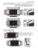
Page 9: ...the desired direction Adjustments Loosen Tighten The satellite speakers are attached to adjustable arms These arms are designed to be extended to match the width of your screen Loosen all 4 fixing po...

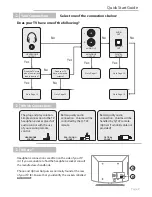
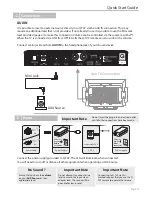
Page 10: ...ontrol Better quality audio connection Volume will be controlled by the Q TV2 remote OPTICAL SOCKET Better quality audio connection Volume will be handled by Q TV2 remote Optical Toshlink cable not pr...

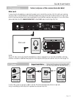
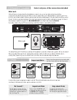
Page 11: ...NOTE If your TV does not mute when the headphone socket is plugged in we recommend either selecting another connection method See page 9 or moving the mini jack connection on Q TV2 See page 15 Connec...

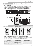
Page 12: ...ad synchronisation between sound and vision using this connection method view the section on SET DELAY Lip Sync Page 14 Select only one of the connections detailed Important Note Connecting to Q TV2 v...

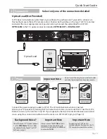
Page 13: ...nnect the power supply provided to Q TV2 The LED will illuminate when connected Silence your TV speakers by turning the TV volume down to zero do not mute the TV Use the Q TV2 Remote to turn up the vo...

Page 14: ...Connect the power supply provided to Q TV2 The LED will illuminate when connected You will need to turn off or silence all other equipment when operating an AUX Source Important Note Connecting to Q T...

Page 15: ...nces when the sound is taken directly from the rear of the TV namely through phono or digital connection the sound can become out of sync with the image due to picture processing delay If you find the...

Page 16: ...propriate volume and from then on use the Q TV2 Remote to control the volume If you are unsure how to do this see the manufactures handbook Alternative Connections Page 15 16V 5A Connect the power sup...

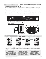
Page 17: ...tive Connections SCART Connect the power supply provided to Q TV2 The LED will illuminate when connected Silence your TV speakers by turning the TV volume down to zero do not mute the TV Use the Q TV2...

Page 18: ...t connected a line level output to a mini jack input Check that you TV s audio out is set to PCM mode Optical Only No Volume Control Mini Jack Connection Make sure that the SOURCE VOLUME switch is in...

Page 19: ...ng point Fixing Rails obstruct TV Screen connections Make sure that you are using the spacers provided Page 6 Remove fixing rails and fit spacers between TV and Rails to clear connections Fixing Rails...

Reviews: