8
9
INSTALLATIoN AND oPErATIoN MANUAL SoLAr MoDULES GENErATIoN 4 (G4) – HANwHA Q CELLS GMBH – NA
INSTALLATIoN AND oPErATIoN MANUAL SoLAr MoDULES GENErATIoN 4 (G4) – HANwHA Q CELLS GMBH – NA
2 PLANNING
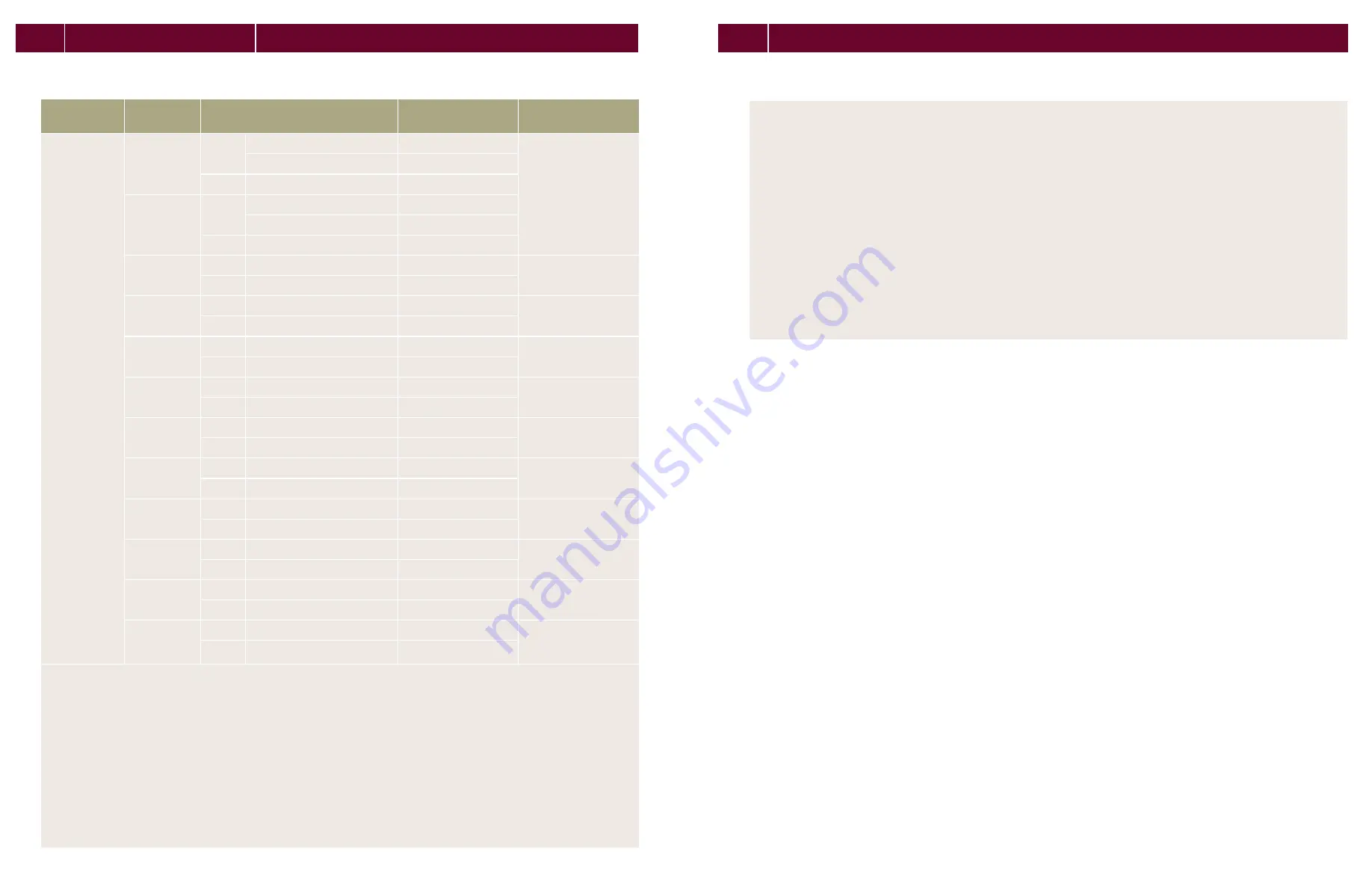
2.3 Mounting options
Specifications
MoDULE TyPE
MoUNTING
oPTIoN
CLAMPING ArEA
1
[IN (MM)]
ALLowED STATIC
LoAD² [PA]
TEST LoAD ACC. IEC
61215 PUSH/PULL [PA]
q.PRO-G4
q.PLUS-G4
q.PRO BFR-G4
q.PRO BLK-G4
CL1
Push
9.84 - 13.78 (250 - 350)
2700
5400/4000
>13.78 - 17.72 (>350 - 450)
1900
Pull
9.84 - 17.72 (250 - 450)
2400
CL1 extended
(min. 0.79 in)
Push
9.84 - 13.78 (250 - 350)
3600
>13.78 - 17.72 (>350 - 450)
3300
Pull
9.84 - 17.72 (250 - 450)
2400
CL3
Push
9.84 - 17.72 (250 - 450)
3300
5400/4000
Pull
9.84 - 17.72 (250 - 450)
2400
CL4
Push
0 - 11.81 (0 - 300)
1350
2400/2400
Pull
0 - 11.81 (0 - 300)
1200
FB1
Push
13.58 (345)
2200
5400/4000
Pull
13.58 (345)
2800
FB2
Push
13.58 (345)
3200
5400/4000
Pull
13.58 (345)
2800
FB1 (9.84 in
(250mm))
Push
9.84 (250)
2900
5400/4000
Pull
9.84 (250)
2800
FB2 (9.84 in
(250mm))
Push
9.84 (250)
3200
5400/4000
Pull
9.84 (250)
2800
IP1
Push
-
3200
5400/4000
Pull
-
3000
IP2
Push
-
1350
2400/2400
Pull
-
1200
CL5 hybrid
clamping
Push
11.81 - (300 - 400)
2700
2400/2400
Pull
11.81 - (300 - 400)
2700
CL2 without
substructure
support
Push
0 - 3.94 (0 - 100)
1200
2400/2400
Pull
0 - 3.94 (0 - 100)
1100
1
Distance between outer edge of module and middle of the clamp.
² Describes the maximum module surface load (vertical to the module surface) regarding safety factors (e.g. EUROCODE). For this
purpose, the load value determined by load tests according to various criteria: laminate overlay, plastic deformation, module failure,
and were divided with a safety factor. The minimum calculated load value corresponds to the maximum permitted load.
UNTING oPTIoN CL1
Ä
Ensure, that the subconstruction does not run below the junction box.
Ä
Ensure, that the connection cables of the junction box don‘t run between laminate and substructure.
MoUNTING oPTIoN CL1 ExTENDED
Ä
Ensure, that there’s distance of minimum 1.77 in (45 mm) between laminate backside and subconstruction respectively
that the distance between module frame backside and substructure is minimum 0.79 in (20 mm).
Ä
Ensure, that the connection cables of the junction box don‘t run between laminate and substructure.
MoUNTING oPTIoN CL4
Ä
Ensure, that the subconstruction runs exactly below the frame, not below the laminate (module less frame).
MoUNTING oPTIoNS FB1 AND FB2
Ä
Ensure, that the connection cables of the junction box don‘t run between laminate and substructure.
•
Use M8 corrosion-proof screws and washers (diameter 0.63 in (16 mm)).


