background image

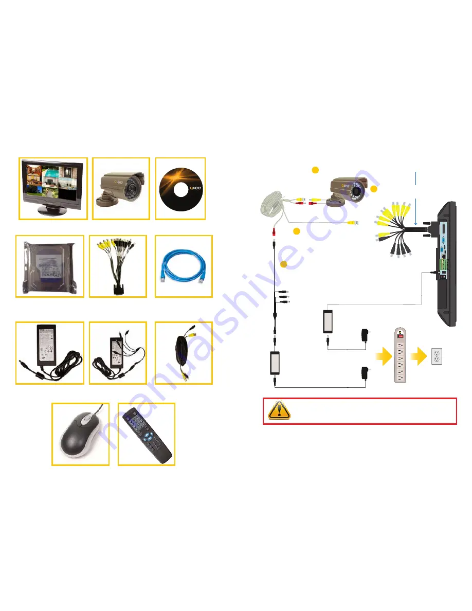
PART 1 - PACKAGE CONTENTS

QC40198 or

QC40196 DVR

Pre-Installed

Hard Drive

Power Supply

for DVR

Video/Audio Dongle

Manual and

Software CD

Ethernet

Cable

Video and Power

Camera Cable

(One per Camera)

Remote

Control

4, 8 or 16

Color Cameras with Stands

Power Supply & 4- or

8-Way Splitter

USB 2.0

Mouse

PART 2 - DVR CAMERA AND POWER CONNECTIONS

Revised 9/8/11

IMPORTANT!


It is STRONGLY recommended to use a surge protector that 

is UL-1449 rated.  Look for a clamping voltage of 330 or lower, a Joule rating 
of at least 400 and a response time of 10 nanoseconds or less.  

The appearance of contents may differ from images shown.

manuals and

software

QC Series

VGA

AUDIO/VIDEO

USB

HDMI

RS232

NET

DC 19V

NO

C

1

NO

C

2

1

2

3

4

5

6

7

8

A

B

CNTRL

12V

STEP 1: Connect the Cameras
              to the Cables

Connect both camera leads to the matching
ends on the power/video cable. 
Repeat for all cameras. 

1B

Connect the Video/Audio Dongle to the Audio/Video port on the bottom of the DVR.

1A

Attach the BNC connector on the 
power/video cable to one of the BNC
connectors marked “Video” on the
Video/Audio Dongle.
Repeat for all cameras. 

1C

Connect the remaining
connector to one of the
ends on the power
splitter. Repeat for all
cameras.

STEP 2:

Connect the single end
of the power splitter to
the included power supply.

STEP 4:

Connect both power supplies to
a surge protector.

STEP 5:

Connect thesurge protector
to an outlet.

STEP 3:

Connect the other power supply to the DVR .

1D

Summary of Contents for QC40196

Page 1: ...8 and 16 Channel H 264 Compression All in One DVRs with Variable CIF and D1 Recording Options Quick Installation Guide For Bundles Featuring the QC40198 or QC40196 Network DVR...

Page 2: ...uals and software QC Series VGA AUDIO VIDEO USB HDMI RS232 NET DC 19V NO C 1 NO C 2 1 2 3 4 5 6 7 8 A B CNTRL 12V STEP 1 Connect the Cameras to the Cables Connect both camera leads to the matching end...

Page 3: ...s for a headphone microphone and for a USB flash drive Using the DVR as a Computer Monitor The DVR s LCD screen can be used as a computer monitor by plugging in a VGA monitor cable from a computer int...

Page 4: ...eds or normal playback 9 Address Click to input device serial number 10 Function Aux Key In 1 channel monitor mode pop up assistant function PTZ control and Video color Switch the PTZ control menu in...

Page 5: ...e symbol and characters are deleted with the key Clicking outside of the keyboard will close it 1 2 3 5 4 6 8 7 9 0 1 4 7 0 2 5 8 3 6 _ 9 a h o u b i p v c j q w d k r x e l s y f m t z g n A H O U B...

Page 6: ...6 3 PICTURE 6 4 PICTURE 6 5 PICTURE 6 6 An example of such a mixed schedule is shown in Picture 6 4 In this example Camera 1 is scheduled to record if motion is detected MD from midnight to 8am and t...

Page 7: ...00 00 R StartTime Type Start Time 08 19 10 13 20 00 End Time 08 19 10 13 26 00 Size KB 52736 1p 2p 3p 4p 1 4 6 5 13 14 15 16 3 2 7 9 11 8 10 12 17 18 19 21 20 The playback screen can be set to displa...

Page 8: ...e KB 52736 1p 2p 3p 4p PART 8 BACKING UP FILES The DVR supports backing up to USB flash drives hard drives burners and SD cards Plug in a USB device and go to the Main Menu and then clicking on the Ba...

Page 9: ...QUESTIONS OR COMMENTS CONTACT US PRODUCT SUPPORT DOWNLOADS FIRMWARE UPDATES MANUALS 24 7 Technical Resources Live Chat M F 9 5 PST www Q See com Support...

Reviews: