background image

40

41

CHAPTER 4  MAIN MENU SETUP

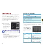
4.6 NETWORK CONFIGURATION

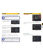
The 

Network Configuration

 window is used to control how your DVR works in a networked 

environment. This section offers a brief overview of how to set up your DVR so that it can be 
remotely monitored from another computer on your network, over the Internet or from mobile 
wireless devices. Full, in-depth instructions on the functions and settings available in this 
window are presented in the 

Remote Monitoring Guide

 which is on the disk that came 

with your system or which can be downloaded from our website at www.Q-See.com. The four 
tabs in this window are 

Network

Sub-Stream

Email

 and 

Other Settings

. If you will only 

be monitoring the DVR from another computer on your network, you will only need to use the 
first three tabs.
It is important that your DVR is connected to your network router and that the router is 
powered on before proceeding.

Network

Network

Substream

Substream

Other Settings

Other Settings

Email

Email

NETWORK

NETWORK

Default

Default

Apply

Apply

Exit

Exit

Test

Test

HTTP Port
Server Port
Obtain an IP address automatically
IP Address
Subnet Mask
Gateway
Preferred DNS Server
Alternate DNS Server
PPPoE
User Name
Password

HTTP Port
Server Port
Obtain an IP address automatically
IP Address
Subnet Mask
Gateway
Preferred DNS Server
Alternate DNS Server
PPPoE
User Name
Password

80
6036

192 . 168 . 001 . 100
255 . 255 . 255 . 000
192 . 168 . 001 . 001
000 . 000 . 000 . 000
000 . 000 . 000 . 000

80
6036

192 . 168 . 001 . 100
255 . 255 . 255 . 000
192 . 168 . 001 . 001
000 . 000 . 000 . 000
000 . 000 . 000 . 000

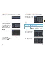
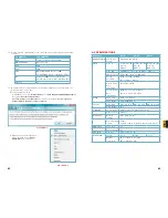
PICTURE 4-35

Network Tab

HTTP Port

 – This is the port the DVR 

will occupy on your computer 
network. When accessing the DVR 
remotely from the Internet, you will 
need to enter your network’s IP 
address (obtained in the next step) 
in the address bar of an Internet 
Explorer window. For example: 
http://192.168.0.25

Optain IP Address Automatically

 – Clicking this box will obtain the IP address, subnet mask, 

and gateway IP from the router.

PPPOE

 – Selecting this enables Point-to-Point Protocol over Ethernet (PPPoE) which allows 
you to directly connect your DVR to the Internet through your modem. Do not use this 
unless required by your Internet Service Provider (ISP) or if you are already connected 
to a router. Contact your ISP for your account information including user name and 
password. The 

TEST

 button will verify that your information is correct.

NOTE!

 The default value is 80. If port 80 is already occupied by another device 

on the network, then another port will need to be selected. Choose another 
number in the same range; 81-89. In this case, you will have to add the port to 
the IP address when entering it into the Internet Explorer window. For example, 
if the port is now 82, then you will need to enter http://192.168.0.25:82

Substream Tab

The substream is the data that is sent to remote monitoring devices. Due to bandwidth 
concerns, these data streams are generally smaller than those sent directly to the DVR itself. 
These streams run in parallel with the main stream sent to the hard drive and they do not 
affect each other.

Definitions and descriptions of network configuration:

Parameter

Definition

HTTP Port

The network port number for accessing the DVR via Internet Explorer. The 
default port is 80

Server Port

The port number for data. The default port is 6036

Static IP

IP Address

The IP address of the DVR on your network

Subnet Mask

The server’s subnet mask

Gateway

The gateway of the router

DNS Server

The address of the Domain Name System (DNS) server

PPPoE

User Name

User name of the broadband account

Password

Password for broadband account

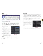
Substream settings are configured in the 
same manner as that used for the primary 
stream settings in the 

Record Bitrate 

tab in 

Section 4.3

 Certain settings will be 

grayed out and cannot be changed due to 
throughput concerns. The definitions are 
repeated for your convenience:

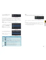
PICTURE 4-36

Parameter

Options

What it Means

Resolution

D1, CIF

D1 = Full TV resolution, CIF = 1/2 D1. D1 takes 

more room on the hard drive than CIF

FPS

1-30

Frames per second. More frames makes for 

smoother video but takes up more room on the 

hard drive.

Encode

VBR, CBR

Variable Bit Rate versus Constant Bit Rate. VBR 

provides better image quality for video with motion 

in it, but at the expense of a larger file size.

Quality

Lowest – Highest

Only available when VBR is selected. The higher 
the quality, the more drive space required.

Max Bitrate

256-2084kbps

Your network may not have enough bandwidth 

to handle maximum rates from all of your 

cameras. Adjusting these settings to suit 

your network will improve performance and 

on-screen image quality.

Summary of Contents for QT454-403-5

Page 1: ...1 User Manual QT4 Series H 264 NETWORK DVR MODEL QT454 QT474 QT428 QT426 QT446 QT4332 ...

Page 2: ...n to warranty and technical support benefits you ll receive notifications of product updates along with free downloadable firmware updates for your DVR Register today at www Q See com Please see the back of this manual for exclusions This manual is written for the QT4 family of DVRs Not all features and capabilities are shared across all models so you may see features described which are not appli...

Page 3: ... 4 5 Alarm Configuration 36 Sensor 36 Motion 37 Video Loss 38 Other Alarm 38 Alarm Out 39 4 6 Network Configuration 40 4 7 User Management 44 4 8 Pan Tilt Zoom PTZ Configuration 45 4 9 Advanced 48 Time Search 49 Event Search 50 File Management 50 Image 51 5 BACKUP 52 6 DVR MANAGEMENT 53 6 1 INFORMATION 53 Event Information 54 Log Information 54 Network Information 54 Online User Information 55 6 2...

Page 4: ... operate this DVR without the cover securely in place Do not attempt to do any repairs to the DVR yourself If there are unusual sounds or smells coming from the DVR unplug it immediately and contact Q See technical support Under no circumstances should the cover be removed while the device is connected to a power source You should only remove the cover to install replace the hard disk drive See Ch...

Page 5: ... files one by one Supports remote playback in Network Client through LAN or internet Supports recording in CIF and D1 resolutions ALARM 1 4 channel alarm output and up to 16 channel depending on model alarm input available Supports scheduling for motion detection and sensor alarm Supports pre recording and post recording Supports linked channels recording once motion or alarm is triggered on desig...

Page 6: ...T Shows power status of the DVR 9 INFRARED WINDOW Receives signals from the remote control 10 BACKUP Enter Backup mode Decreases the value in Setup mode 11 USB PORT Used for external USB backup devices The mouse will not function in this port ITEM NAME FUNCTION 1 AUDIO IN 4 Channels of audio input 2 VIDEO IN Video input from up to 4 cameras 3 AUDIO OUT Audio output for amplified speaker 4 SPOT OUT...

Page 7: ... 2 Channels of audio input 2 VIDEO IN Video input from up to 4 cameras 3 VIDEO OUT BNC connector for TV or monitor 4 VGA PORT VGA output for 19 or larger monitor 5 POWER SWITCH Use to turn on the DVR as well as to turn off after powering down from within the GUI 6 AUDIO OUT BNC Audio output for amplified speaker 7 LAN Network ethernet port 8 USB PORT For the USB mouse 9 PTZ Connections for Pan Til...

Page 8: ... selection 11 DIRECTION MULTISCREEN 1 Navigate through on screen options 2 Change screen display mode between 1 4 9 and 16 channels 12 USB USB port to connect USB flash or external hard drives to update firmware or back up recordings ITEM NAME FUNCTION 1 AUDIO OUTPUT Connection for audio output connect to an amplified speaker 2 AUDIO IN 4 Channel audio input for cameras equipped with audio 3 VGA P...

Page 9: ...igate through on screen options 2 Change screen display mode between 1 4 9 and 16 channels 11 ENTER Confirm selection 12 USB USB port to connect USB flash or external hard drives to update firmware or back up recordings ITEM NAME FUNCTION 1 VIDEO OUT Video output for connecting to TV BNC or monitor 2 SPOT Connect to another monitor as an auxiliary output channel This monitor will only display vide...

Page 10: ...deo output mode 17 CONTROL KNOB Outer ring navigates through menus Inner knob increases or decreases speed of fast forward or rewind 3 5 7 4 1 2 6 9 8 10 11 12 14 16 13 17 15 16 BACK PANEL 1 2 4 6 9 8 7 10 11 14 12 17 16 15 13 18 5 3 ITEM NAME FUNCTION 1 VIDEO OUT BNC connector for TV or monitor 2 VIDEO IN BNC connectors for up to 16 cameras 3 eSATA 2 Connection for external eSATA hard drive for b...

Page 11: ... video output mode 17 CONTROL KNOB Outer ring navigates through menus Inner knob increases or decreases speed of fast forward or rewind 3 5 7 4 1 2 6 9 8 10 11 12 14 16 13 17 15 16 BACK PANEL ITEM NAME FUNCTION 1 VIDEO OUT BNC connector for TV or monitor 2 VIDEO IN BNC connectors for up to 32 cameras 3 SPOT OUT Connect to another monitor as an auxiliary output channel This monitor will only displa...

Page 12: ...ing the mouse controls reserving the remote control for operations such as live viewing file search and playback It uses two AAA sized batteries If the remote s performance degrades check the batteries as well as that the IR receiver window on the DVR is unobstructed 2 2 MOUSE The USB mouse can only be used when connected to the USB port on the rear panel The system will not recognize it when conn...

Page 13: ...lowing chapters Menu Opens the Main Menu Screen Display Mode Choose the number of channels you wish to view at once Channels without attached cameras will display Video Loss Clicking on the upward pointing arrows to the right of each icon will allow you to select which channels to view in that mode Dwell Enable disable the automatic cycling between channels Color Adjust the brightness hue saturati...

Page 14: ...Exit Frame Advance Next Record Playback Progress Bar Zoom Zoom Color Color The controls operate in a similar fashion to those of a conventional DVR or other video playback device but with a few additional commands available to you Previous Next Record Moves to the prior or following recorded event respectively Fast Forward Rewind In addition to their normal operation clicking on these buttons mult...

Page 15: ... CHANNEL SELECT menu Users can check any or all channels between 1 and 16 depending on your model to display the live feeds Click the box to confirm the settings before closing the CHANNEL SELECT menu by clicking on the button MAIN MENU Selecting the MENU icon on the left of the CONTROL BAR or pressing the MENU button on the DVR and remote control open the MAIN MENU PICTURE 4 4 PICTURE 4 6 Clickin...

Page 16: ...ur system s clock current by allowing it to occasionally receive updates from the selected server 4 2 LIVE CONFIGURATION Live configuration includes four submenus Live Main Monitor Spot and Mask Live Tab Use this menu to set camera names and adjust picture colors brightness hue saturation and contrast for optimal picture results PICTURE 4 9 PICTURE 4 10 You can individually name cameras by highlig...

Page 17: ...ve sets of options Enable Record Bitrate Time Stamp and Recycle Record Enable Tab Select some or all of the cameras to record to the DVR You can set up to four cameras to record audio in addition to video You can globally select all the cameras regardless of their individual settings by selecting the All box below each column Record Bitrate Tab Set up the resolution quality encoding quality and ma...

Page 18: ...RE 4 23 4 4 SCHEDULE CONFIGURATION Your DVR is configured to record whenever motion is detected If this is your desired setting then you will not need to make any changes However you may configure each channel to record at specific times based on time of day motion detection or other sensor input There are three tabs Schedule Motion and Sensor Schedule Tab The schedule for automatic recording can ...

Page 19: ...d whether a signal will be sent via the ALARM OUT port MOTION Motion Tab As with the Alarm function above it incorporates hold time and can trigger procedures Select which cameras you wish to start recording on motion detection Set the holding time which determines the length of time the cameras continue recording after motion stops To Record allows you to determine which cameras will begin record...

Page 20: ...ts that you wish to occur in the event that a video input is lost Both Alarms and PTZ events can be scheduled as in the Sensor menu above OTHER ALARM In this menu you can set the DVR to alert you to a full Hard Drive IP Conflict on the network or a Disconnection You can set the response as well as at what threshold of remaining disk space you wish to be alerted ALARM OUT Set how the alarms are han...

Page 21: ... are already connected to a router Contact your ISP for your account information including user name and password The TEST button will verify that your information is correct NOTE The default value is 80 If port 80 is already occupied by another device on the network then another port will need to be selected Choose another number in the same range 81 89 In this case you will have to add the port ...

Page 22: ...o receive alerts It is strongly advised that you do not use the same address that the DVR is using to send alerts PICTURE 4 37 Advanced Attaching Image Amount The alert e mails can include up to three images Snap Time Interval The interval of the images can range from every second to every five seconds Other Settings Commercial ISPs provide their customers with dynamic addresses IP numbers These n...

Page 23: ...tton Modify a user s password The admin password may be changed The default is 123456 4 8 PAN TILT ZOOM PTZ CONFIGURATION If you are connecting optional Pan Tilt Zoom cameras the controls are set from this window in the Serial Port and Advanced tabs Serial Port Tab You will need to consult your PTZ camera s manual for details regarding protocol and baud rate Please note that the DVR may support mo...

Page 24: ...t all the way to the top of the order Move a preset point up one position in the list Move a preset point down one position in the list Move a preset point to the bottom of the order Cruise Selecting a Setting button from the Cruise column will open the Cruise window Select Add or double click on an existing line to modify and the CRUISE PRESET window will open Delete will remove a selected cruise...

Page 25: ...mobile or external storage devices and recorded onto the DVR PICTURE 4 50 4 10 FILE SEARCH PLAYBACK AND MANAGEMENT Access the recordings on the DVR play them back and backup the recordings to an external storage device NOTE Throughout this window if the screen resolution is VGA 800 600 the time search interface will show a Hide button Clicking on this button will expand or minimize the entire inte...

Page 26: ...arch Delete Delete Lock Lock Save Save Save All Save All Time Search Image Event Search File Management Start Time 3 13 End Time 12 23 2010 12 23 2010 00 00 00 00 00 00 23 59 59 23 59 59 25 12 23 2010 12 23 2010 25 PICTURE 4 57 IMAGE This tab functions much as the Event Search tab by allowing you to search for and view the still images captured when you click on the Snapshot icon on the Control Ba...

Page 27: ...ting and ending times total size of the files and whether you have space available on the receiving storage media You can select which type of device you are recording to as well as what type of file you will be creating NOTE If you save the file s using the DVR selection two folders are created when backing up the events to a USB storage device One will contain the video files while the other lab...

Page 28: ...s the list of online users Disconnect The Administrator can disconnect a selected user from the DVR That PC will not be able to access the device for five minutes thereafter 6 2 MANUAL ALARM This displays the configuration of the manual alarm PICTURE 6 8 PICTURE 6 9 6 3 DISK MANAGEMENT This window displays information on the drive mounted within the DVR including size available space and status Th...

Page 29: ...sh drive HARD DISK DRIVE CHAPTER 7 Your DVR uses a standard SATA Serial Advanced Technology Attachment hard disk drive and will support drives up to 2TB terabytes These drives are the current industry standard and may be purchased wherever computer parts are sold Depending on where you purchased your DVR your hard drive may already be installed But we recognize that you may wish to upgrade or repl...

Page 30: ...f hard drive that you ll need VIDEO FORMAT RESOLUTION FRAME RATE FPS VIDEO QUALITY BIT RATE kbps SPACE USED MB h NTSC CIF 30 Highest 1000k 465 Higher 768k 297 Medium 512k 230 Low 384k 173 Lower 256k 115 Lowest 128k 56 D1 7 5 Highest 500k 228 Higher 375k 128 Medium 250k 117 Lower 192k 75 Lowest 128k 61 PAL CIF 25 Highest 1000k 466 Higher 768k 295 Medium 512k 235 Low 384k 175 Lower 256k 112 Lowest 1...

Page 31: ...nd displays please wait all the time a First possible reason hard drive power cable and or data cable are not securely connected Solution Please check the cable connections and make sure they are secure if still not working please unplug them and then plug them in again b Second possible reason The system is having problems reading the hard drive Solution Try reformatting the current drive or re p...

Page 32: ...OSITE 1 0V p p 75Ω BNC x 2 VGA x 1 VGA Resolution 1280x1024 1024x768 800x600 Record Resolution NTSC 352x240 704x480 PAL 352x288 704x576 Display Frame Rate per camera 704x480 at 30FPS Record Frame Rate per camera NTSC D1 7 5FPS CIF 30FPS PAL D1 6 25FPS CIF 25FPS AUDIO Audio Input 8dB 22k RCA X4 Audio Output 8dB 92dB RCA X1 ALARM Alarm Input NO or NC 4CH NO or NC 8CH NO or NC 16CH Alarm Output 1CH S...

Page 33: ... QT4332 COMPRESSION Compression Format Standard H 264 Baseline VIDEO Video In Composite 1 0V p p 75Ω BNC x 4 Composite 1 0V p p 75Ω BNC x 16 75Ω BNC x 8 Composite 1 0V p p 75Ω BNC x 32 Video Out COMPOSITE 1 0V p p 75Ω BNC x 1 VGA x 1 COMPOSITE 1 0V p p 75Ω BNC x 1 VGA x 1 Loop Out x 2 COMPOSITE 1 0V p p 75Ω BNC x 1 VGA x 1 HDMI x 1 VGA Resolution 1280x1024 1024x768 800x600 1920x1080 1280x1024 1024...

Page 34: ...S OR COMMENTS CONTACT US Digital Peripheral Solutions Inc 8015 E Crystal Drive Anaheim CA 92807 PRODUCT SUPPORT DOWNLOADS FIRMWARE UPDATES MANUALS 24 7 Technical Resources Live Chat M F 9 5 PST www Q See com Support ...

Reviews: