background image

INSTALLATION 

LED POWER SUPPLY - QOM-eLED+DALI-DT6

© 2021 Q-Tran Inc. All rights reserved | 155 Hill St. Milford, CT 06460 | 203-367-8777 | sales@q-tran.com | www.q-tran.com 

Specification subject to change. Rev-11-15-22

WARNING:

 Risk of electrical shock. May result in serious injury or death. Disconnect power before servicing or installing. 

CAUTION:

 The device may only be connected and installed by a qualified electrician. All applicable regulations, legislation and building codes 


  must be observed. Incorrect installation of the device can cause irreparable damage to the device and the connected LEDs. 


V-

V-

V+

V+

+

1(-)

2(-)

3(-)

4(-)

12-36VDC IN

LED groups

LED 

V-

V-

V+

V+

+

1(-)

2(-)

3(-)

4(-)

12-36VDC IN

LED groups

LED 

Primary Wiring

Control Wiring: 

DALI Connections

Secondary Wiring

NEU

GND

HOT

LED DRIVER  (120-277V)

V-

V-

V+

V+

+

R-

G-

B-

W-

D1+

D2+

D1-

D2-

LED groups

12-36VDC IN

D2-

D1-

D2+

D1+

V+

V+

V-

V+

V-

B-

R-

G-

W-

LED groups

12-36VDC IN

DALI Signal

 in/out

V-

V-

V+

V+

+

R-

G-

B-

W-

D1+

D2+

D1-

D2-

LED groups

12-36VDC IN

DALI Signal

 in/out

DALI Signal

 in/out

DALI

Contr

oller

D1+

D2+

D1-

D2-

DALI 

IN

DALI OUT

2-Wire default is 1 address

3-Wire default is 2 address

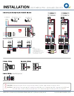
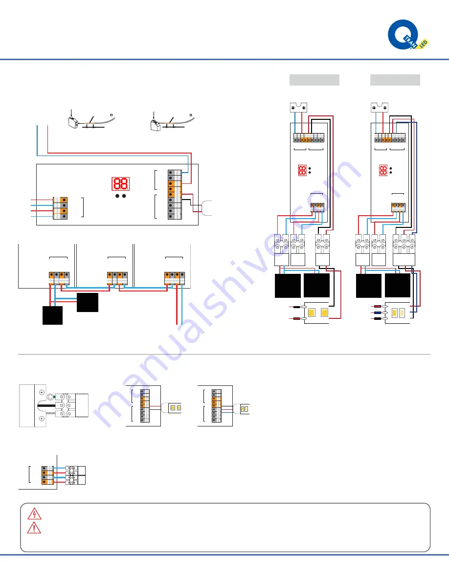
Connecting and Configuring the DALI-DT6 Decoder

To DALI Controller

V-

V-

V+

V+

+

1(-)

2(-)

3(-)

4(-)

12-36VDC IN

LED groups

D1+

D2+

D1-

D2-

DALI Signal

 in/out

D1+

D2+

D1-

D2-

{

12-36VDC IN

-

+

1

0.2-1.5 mm

2

0.35 inch

0.5-1.5 mm

2

AWG 20-16

0.35 inch

AWG 24-16

VDC and LED connectors:

Other connectors:

LED 

V- V- V+ V+ + 1(-) 2(-) 3(-) 4(-)

12-36VDC IN

LED groups

D1+

D2+

D1-

D2-

DALI Signal

 in/out

V- V- V+ V+ + 1(-) 2(-) 3(-) 4(-)

12-36VDC IN

LED groups

D1+

D2+

D1-

D2-

DALI Signal

 in/out

V- V- V+ V+ + 1(-) 2(-) 3(-) 4(-)

12-36VDC IN

LED groups

D1+

D2+

D1-

D2-

DALI Signal

 in/out

DALI

Controller

*By Others

DALI Bus

Power Supply

*By Others

V- V- V+ V+ + 1(-) 2(-) 3(-) 4(-)

12-36VDC IN LED groups

D1+

D2+

D1-

D2-

DALI Signal

 in/out

DALI 

OUT

DALI 

IN

DALI

Controller

*By Others

DALI Bus

Power Supply

*By Others

-

+24V

-

+

V- V- V+ V+ + 1(-) 2(-) 3(-) 4(-)

D1+

D2+

D1-

D2-

12-36VDC IN LED groups

DALI Signal

 in/out

DALI 

OUT

DALI 

IN

DALI

Controller

*By Others

DALI Bus

Power Supply

*By Others

Warm

Cool

+24V

+24V W C

3-Wire

2-Wire

2A - 2 Addresses

1A - 1 Addresses

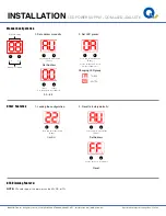
NOTE:

2-Wire default is 1 address
3-Wire default is 2 addresses
For customization or pre-programming 
contact a local sales rep.
DALI commissioning to be performed by 
a third party at time of installation.

Summary of Contents for QOM-eLED+DALI-DT6

Page 1: ... work on a sturdy wooden or fiberglass ladder This power supply must be installed according to the National Electric Code and local codes and ordinances This power supply is to be installed and serviced only by an licensed electricians This power supply is to be installed so that it is not likely to be contacted by people To avoid a hazard to children account for all parts and destroy all packagin...

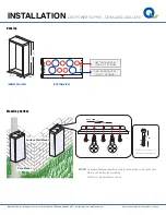
Page 2: ...Rev 11 15 22 Housing Mounting Options BOTTOM VIEW ISOMETRIC VIEW 1 36 KNOCKOUT 4X FOR 1 FITTINGS 1 07 KNOCKOUT 5X FOR 3 4 FITTINGS 4 90 14 5 15 4 9 22 4 90 NOTE To order additional lengths of wire for connection in the secondary Please call factory for availability QOM must be installed as shown Pole Mount Surface Wall Mount 2 00 0 25 1 4 x2 wood screw or LAG bolt recommened 1 82 3 38 3 14 ...

Page 3: ... 3 Wire default is 2 address Connecting and Configuring the DALI DT6 Decoder To DALI Controller V V V V 1 2 3 4 12 36VDC IN LED groups D1 D2 D1 D2 DALI Signal in out D1 D2 D1 D2 12 36VDC IN 2 1 0 2 1 5 mm2 0 35 inch 0 5 1 5 mm2 AWG 20 16 0 35 inch AWG 24 16 VDC and LED connectors Other connectors LED V V V V 1 2 3 4 12 36VDC IN LED groups D1 D2 D1 D2 DALI Signal in out V V V V 1 2 3 4 12 36VDC IN ...

Page 4: ...2 Press and hold either button Use the buttons to set address 1 2 Set Address 5 sec 2 Set LED groups Changing LED group 1A SW 2A TW 1 2 Press and hold both button Use the first button to set the amount of addresses 5 sec 1 Locking the configuration Confirm 1 2 Press and hold either button 5 sec 2 Reset to factory defaults Reset 1 2 1 2 Set Address Press and hold either button 5 sec Use the buttons...

Page 5: ...D HOT DALI IN DALI OUT V V V V 1 2 3 4 12 36VDC IN LED groups D1 D2 D1 D2 DALI Signal in out V V V V 12 36VDC IN LED groups D1 D2 D1 D2 DALI Signal in out V V V V 12 36VDC IN LED groups D1 D2 D1 D2 DALI Signal in out 1 2 3 4 1 2 3 4 SECONDARY PRIMARY DA DA Red 24V Black Negative LEAD WIRE NEU GND HOT DA DA Red Blue To next power supply LED LED LED DALI Controller By others DALI Bus Power Supply By...

Page 6: ... 4 pi du sol Suitable for use with submersible luminaires or submersible pumps Convient pour une utilisation avec des luminaires submersibles ou des pompes submersibles Suitable for wet locations Convient aux emplacements mouillé CAUTION This control unit has more than one power supply point disconnect all power supplies before servicing ATTENTION Cette unité de contrôle a plus d un point d alimen...

Reviews: