background image


QT

300

Revision:


1


QT

300


User


Manual


Page


3


of


11


Q5X


Systems,


Inc.


2018


FCC


Notices:


Information


to


users:


This


device


complies


with


Part


15


of


the


FCC


Rules.


Operation


is


subject


to


the


following


two


conditions:


(1

.

)


This


device


may


not


cause


harmful


interference


,


and


(2

.

)


This


device


must


accept


any


interference


received,


including


interference


that


may


cause


undesired


operation.


N

OTE

:


This


equipment


has


been


tested


and


found


to


comply


with


the


limits


for


a


Class


B


digital


device,


pursuant


to


part


15


of


the


FCC


Rules.


These


limits


are


designed


to


provide


reasonable


protection


against


harmful


interference


in


a


residential


installation.


This


equipment


generates,


uses


and


can


radiate


radio


frequency


energy


and,


if


not


installed


and


used


in


accordance


with


the


instructions,


may


cause


harmful


interference


to


radio


communications.


However,


there


is


no


guarantee


that


interference


will


not


occur


in


a


particular


installation.


If


this


equipment


does


cause


harmful


interference


to


radio


or


television


reception,


which


can


be


determined


by


turning


the


equipment


off


and


on,


the


user


is


encouraged


to


try


to


correct


the


interference


by


one


or


more


of


the


following


measures:


Reorient


or


relocate


the


receiving


antenna.


Increase


the


separation


between


the


equipment


and


receiver.


Connect


the


equipment


into


an


outlet


on


a


circuit


different


from


that


to


which


the


receiver


is


connected.


Consult


the


dealer


or


an


experienced


radio/TV


technician


for


help.


Warning:


Changes


or


modifications


not


expressly


approved


by


Quantum5X


Systems


Inc,


could


void


the


user’s


authority


to


operate


the


equipment.


Summary of Contents for QT-300

Page 1: ...QT 300 Module User Manual Rev 1 ...

Page 2: ...QT 300 Revision 1 QT 300 User Manual Page 2 of 11 Q5X Systems Inc 2018 History Rev 1 January 2 2018 Original ...

Page 3: ...requency energy and if not installed and used in accordance with the instructions may cause harmful interference to radio communications However there is no guarantee that interference will not occur in a particular installation If this equipment does cause harmful interference to radio or television reception which can be determined by turning the equipment off and on the user is encouraged to tr...

Page 4: ...tter IC 4614A QT300 has been approved by ISED to operate with the antenna types listed below with the maximum permissible gain indicated Antenna types not included in this list having a gain greater than the maximum gain indicated for that type are strictly prohibited for use with this device Le présent émetteur radio IC 4614A QT300 a été approuvé par Industrie Canada pour fonctionner avec les typ...

Page 5: ...eet the following conditions Otherwise additional FCC ISED approvals must be obtained Mobile Application 1 This equipment complies with radiation exposure limits set forth for an uncontrolled environment This equipment should be installed and operated with minimum distance 20cm between the radiator and your body 2 This transmitter must not be co located or operating in conjunction with any other a...

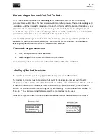
Page 6: ...radiators FCC section 15 107 15 109 and ISED ICES 003 before declaring compliance to Part 15 of the FCC Rules and ISED ICES 003 The module integrator may not 1 Alter modify or remove the module case 2 Make changes to the Circuit Card Assembly of the module Failure to comply with these restrictions will result in violation of the FCC certification Labeling of the End Products The modular transmitte...

Page 7: ...f the SEL select button and the adjacent Alpha Numeric 16 position dial are used to access and make changes to the various device parameters The table below outlines each menu Menu Input Action SET FREQ A Single press Allows user to Set the 6 frequency digits READ FREQ B Single press Reads the 6 digits of the tuned frequency SET PWR C Single press Allows user to Set RF output power level READ PWR ...

Page 8: ...ouble Flash DF Rapid Flash error a rapid Red Flash indicates the first digit is wrong it can only be 4 5 or 6 If it s a rapid Green Flash then the second digit is out of range etc To program in 470 025 Mhz turn the dial to position A press the SEL button then do the following Red SF turn dial to 5 press SEL button Green SF turn dial to 7 press SEL button Orange SF turn dial to 5 press SEL button R...

Page 9: ...be solid Red for 1 second to indicate the fourth digit is 0 After a short pause the LED will flash Green 2 times to indicate the fifth digit is 2 After a short pause the LED will flash Orange 5 times to indicate the third digit is 5 Once the sixth digit has been displayed the LED will resume displaying the battery status Set Output Power To set the output power turn the dial to the letter C and pr...

Page 10: ...splay the 3 digits of the current firmware version For example the firmware version is 0 2 2 The LED will turn on Red solid for 1 second to indicate the first digit is 0 After a short pause the LED will flash Green 2 times to indicate the second digit is 2 After a short pause the LED will flash Orange 2 times to indicate the third digit is 2 Once the third digit has been displayed the LED will res...

Page 11: ...e 50 Ω Impedance RF Power Output see table below Item Product Name Max RF Power 1 QT 300 Module 250 mw 2 PlayerMic Body Mounted Only 100 mw 4 AquaMic Body Mounted Only 250 mw 7 Incognito Body and head Mounted 100 mw 9 BeltMic Body Mounted Only 250 mw Antenna impedance 50 Ω Impedance Technical Data QT 300 Module Power Requirements 3 7V Current Drain 140 mA Max Input Audio Signal 1 VRMS Audio Gain A...

Reviews: