Optimizer4D Technical Specifications
5 / 27
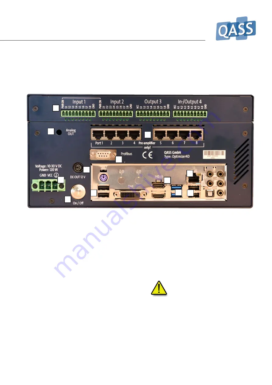
1. GB Ethernet
2. Power connector (for use with power adapter or for direct
connection to power supply via machine)
3. PLC connectors and I/O-Ports
4. Power switch - power - only use software to turn off the
system
5. RJ45-connectors for pre-amplifiers
6. USB 3.0-connectors
7. HDMI
8. USB 2.0-connectors for display
9. Power supply for display
10. Profibus connector
11. Analogue out
The
display
comes with four connectors: a. the HDMI-port
(7, do not use the lower port that comes with specific
versions); b. the USB-2.0-connector (8, marked with black
color inside of the socket; do not use the blue sockets); c.
the power supply (9).
Connectivity options
I/O-Ports:
If you use an output-port of any kind (I/O 4 or
Output 3), it‘s essential to bridge the three GND (ground)
connectors.
In order to
power the device on
you can use the power
switch (4) or briefly connect the unmarked sockets in Input
1 and Input 2.
Attention!
Do not confuse the RJ45-Ports (5) with the
Ethernet port (1)! Malfunction or even destruction of the
device is possible if a ethernet plug is connected to the
pre-amplifier-ports (5)!
3
2
1
4
5
6
7
8
8
9
10
11


