


11.Trouble shooting
TROUBLE
PROBABLE CAUSES
SUGGESTED REMEDY
1. Fan will not start
A/ Fuse or circuit breaker blown.
B/ Loose power line connections
to the fan.
C/ Speed controller not in correct
position.
A/ Check main and branch circuit
fuses or circuit breakers.
B/ Check line wire connections to fan
C/ Check speed controller’s position.
2. Fan sound noisy
A/ Top canopy touching ceiling.
B/ Loose fan blade screws.
C/ Ceiling fan not secured against
ceiling.
D/ Incorrect speed controller.
A/ Lower Canopy from ceiling to
ensure minimum 3 mm clearance.
B/ Re-tighten all screws on fan blades
but never over-tighten.
C/ Re-tighten all screws in the
hanging bracket or plate.
D/ Change the controller to the one
supplied.
3. Mechanical Noise
A/ Allow at least for 8 hours
settling-in period.
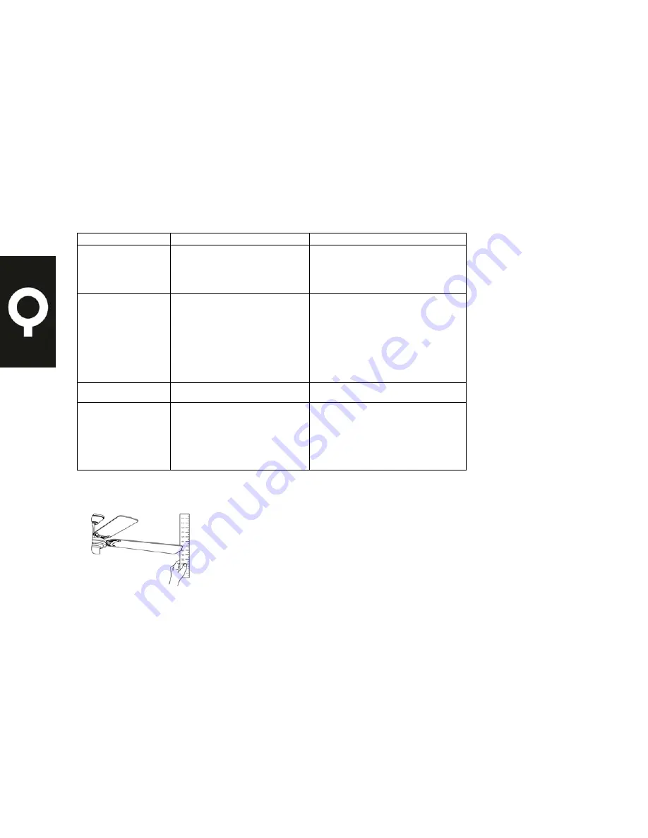
4. Fan Wobbles
A/ Fan blades are not horizontal to
ceiling.
B/ Blade screws are loose.
A/ Measure from ceiling to tip of
blades, then rotate fan so all blades
are checked for equal height from
ceiling (not adjustments may be made
by slight pressure up or down on
blade holders). Make sure all screws
are securely fastened.
DYNAMIC BLADE BALANCE KIT
YARDSTICK
MEASURING
POINT
P.10


