6
—
TECHNICAL DATA
UNIVERSAL ROBOTS MANUAL — MAR 9, 2023 — RELEASE: V1.0.3
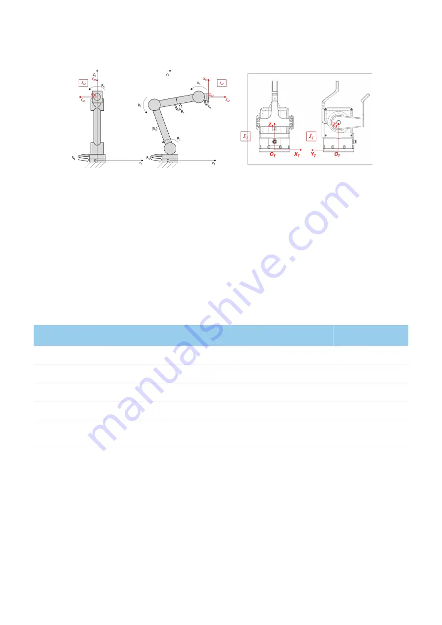
Figure 1. —
Robot Tool Coordinate System
On the left, it is represented the mechanical interface coordinate system
Σ
M
(O
M
; X
M
, Y
M
, Z
M
)
of
an
articulated robot, as defined by ISO 9787:2013. In particular, the center of the coordinate system,
O
M
, is
on the interface surface of the robot tool flange and the
Z
M
axis
is coincident with the tool flange axis of
symmetry. R
i
is the i-th revolute joint of the robot
and
(O
1
; X
1
, Y
1
, Z
1
)
is
the base coordinate system of the
robot.
On the
right, there
is the Tool Coordinate
System,
Σ
T
(O
T
; X
T
, Y
T
, Z
T
)
, of the qbSoftClaw and the
center,
O
T
,
coincides with the center of mass of the device and its position is defined by the distance
from
O
M
.
The
Z
T
axis
is normal to the palm, outgoing positive, and
the
Y
T
axis
follows the proximal-distal direction and
orientation.
3.3 Mechanical characteristics
MINIMUM
NOMINAL
MAXIMUM
Payload
[kg]
—
—
3.70
Grasping force
[N]
0.5
—
64.0
Grasping time
[s]
—
—
1.0
Releasing time
[s]
—
—
1.0
Look at the graph for details. The grasping force in the graph refers to the component along the line joining
the centers of the two pads, so it depends on the size of the object


