41
12
PV connection (H4 and H5 only)
• Before connecting or disconnecting the PV cables, make sure the PV switch is
turned off.
• Make sure the PV cables are connected with the correct polarity.
• Make sure the open circuit voltage does not exceed the inverter input limit 600 V.
Otherwise, the status of inverter is fault.
The lead wires from the PV modules are directly connected to Q.HOME CORE. For the connectors
(PV1+, PV1-, PV2+, and PV2-) between the distribution box and the Q.HOME CORE input, MC4 type
connectors are used.
12.1 Assembling the PV Connector
Stäubli PV-KBT4/6II-UR, PV-KST4/6II-UR is used for the PV connector.
Note
For information about the PV cable specification, see "6.2 Power Cable Specification" on page 27.
To assemble the PV Connector:
1
Strip the cables.
• Strip length: 6 to 7.5 mm
2
Crimp the stripped cables using a crimping plier.
3
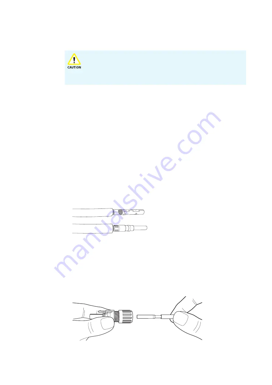
Check the crimped cables to make sure that:
• All of the strands are captured in the crimp sleeve,
• The crimp sleeve is not deformed or missing any portion of the crimp flaps,
• The crimp is symmetrical in form.
4
Insert the crimped-on contact into the insulator of the male or female coupler until engaged.
• Usually a “click” sound will be heard once fully inserted.
• Pull gently on the lead to check that the metal part is correctly engaged.


