INSTALLATION AND OPERATION MANUAL SOLAR MODULES Q.MAXX-G4
INSTALLATION AND OPERATION MANUAL SOLAR MODULES Q.MAXX-G4
16
17
4 Electrical Connection
4.2 Electrical installation safety
4 Electrical Connection
4.3 Connection of modules
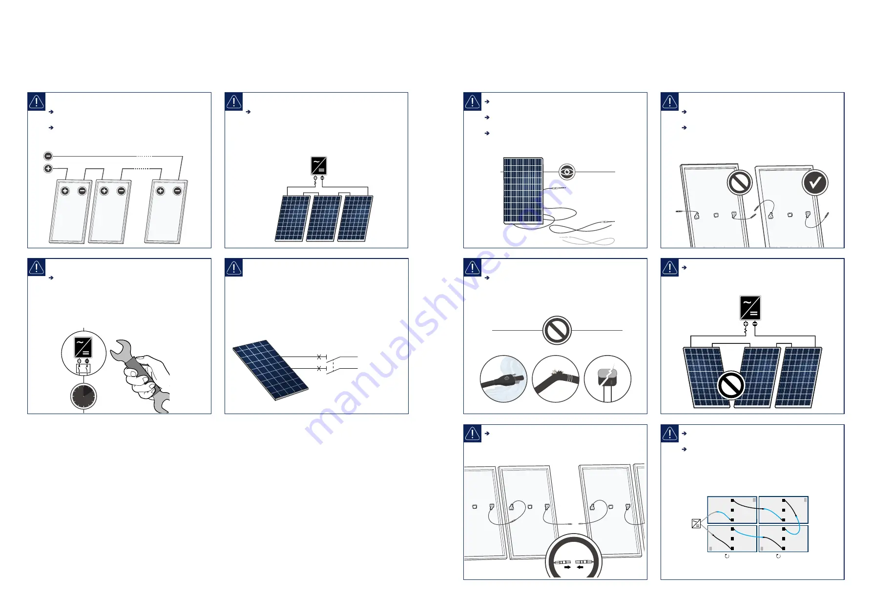
Danger! Risk of fatal injury due to electric shock!
Be sure to maintain the time intervals as specified by
the inverter manufacturer between switching off the
inverter and beginning any further work.
Danger! Risk of fatal injury due to electric shock!
Never plug or unplug the cable when under load.
Modules must not carry any current.
1. Switch off the inverter.
OFF
2. Switch off the DC circuit breaker.
3. Measure shutdown in DC String.
(no DC current flow).
4. Disconnect plugs by the use of appropriate
and qualified tools of the manufacturer.
5. When connecting the modules proceed in
reverse order.
Danger! Risk of fatal injury due to electric shock!
Electrical work may only be performed by qualified
and skilled personnel (see page 3).
Ensure correct polarity.
Use solar cables for the connection at the junction
box outlet.
Only interconnect connectors of the same type and
manufacturer.
Use minimum 4 mm
2
copper wires insulated for a
minimum of 90 °C for field connections.
Note! Module damage may occur!
Ensure that the cabling is not under mechanical stress
(Comply with bending radius of ≥60 mm).
Ensure that the cables do not run between module
and mounting rail or structure (danger of pinch).
Do not connect modules with different orientations or
angles of inclination in the same string.
Ensure for a tight connection between the plugs.
Plugs click together audibly.
click
Danger! Risk of fatal injury due to electric shock!
Ensure that all electrical components are in a proper,
dry, and safe condition.
To avoid complex cabling arrangements, it is often
advantageous to rotate some modules 180°.
Module orientation can clearly be identified from the
front side by the serial number and barcode labelled
behind the module glass on the side with negative
connection cable.
Inverter
180°
180°
SOLAR


