background image

2

ENGLISH

Safety and Regulatory Information

Copyright

1.1 

All specifications and figures are subject to change without prior notice. Actual products may look 

different from the photos.
All trademarks and logos mentioned in this guide are the properties of their respective holders.
Copyright 

©

 2017 Quanta Computer Inc. All rights reserved.

About the Manual

1.2 

This installation guide is meant for network administrators with inept knowledge in network 

management.

To avoid personal injury or property damage, before you begin installing the product, read, observe, 

and adhere to all the following safety instructions and information. 
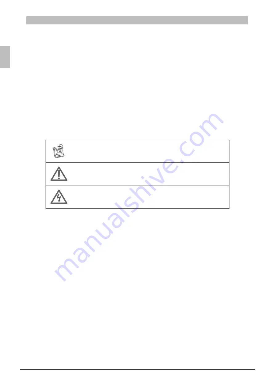
The following symbols are used throughout the guide to highlight important information and may be 

marked on the product and  / or the product packaging.

Manual Conventions Icon

Table 1-1: 


NOTE:


Indicates useful information.

WARNING:


Indicates safety information that if ignored may cause the system to 

malfunction or damage other equipment.

CAUTION:

Indicates safety information that if ignored may cause personal injury or 

death.

Intended Application Uses

1.3 

This product was evaluated as Information Technology Equipment (ITE). which may be installed in 

offices, schools, computer rooms, and similar commercial type locations. The suitability of this product 

for other product categories and environments (such as medical, industrial, residential, alarm systems, 

and test equipment), other than an ITE application, may require further evaluation.

Safety Information

1.4 

Switch Safety Information

1.4.1 

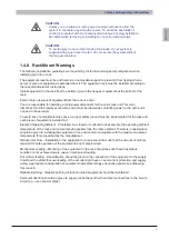
To reduce the risk of body injury, electrical shock, fire, and equipment damage, read this document 

and observe all warnings and precautions before installing or maintaining your switch. 

In the event of a conflict between the information in this document and the information provided with 

the product or on the website of a particular product, the product documentation takes precedence.

The switch should be integrated and serviced only by technically qualified persons.

You must adhere to the guidelines in this guide and the assembly instructions in the switch manuals 

to ensure and maintain compliance with existing product certifications and approvals. Use only the 

described, regulated components specified in this guide. Use of other products / components will void 

the UL Listing and other regulatory approvals of the product, and may result in noncompliance with 

product regulations in the region(s) in which the product is sold.

Summary of Contents for QuantaMesh T1048-LB9

Page 1: ...QuantaMesh T1048 LB9 Network Switch Layer 2 3 Managed 1 10G Switch Installation Guide...

Page 2: ...5 2 Product Regulatory Compliance Markings 11 Chapter 2 Introduction 12 2 1 Front Panel 13 2 1 1 LED Description 13 2 2 Rear Panel 16 2 3 Package Contents 16 Chapter 3 Hardware Installation 17 3 1 Un...

Page 3: ...y Install Vendor OS 32 Chapter 5 Troubleshooting 34 5 1 Troubleshooting 35 5 1 1 Diagnostic Switch Indicator 35 5 1 2 Power and Cooling Problems 35 5 1 3 Installation 35 5 1 4 In Band Access 36 5 2 Re...

Page 4: ...e T Port 22 Figure 3 8 SFP Port Numbering 22 Figure 3 9 Connect SFP Module 23 Figure 3 10 Connect to Console Port 24 Figure 3 11 Connect to Management Port 25 Figure 4 1 Boot Up Console Screen 27 Figu...

Page 5: ...Table 1 2 Product Regulatory Compliance Markings 11 Table 2 1 Base T Port LEDs 13 Table 2 2 SFP Port LEDs 14 Table 2 3 Function and Management Port LEDs 15 Table 2 4 Power Supply LEDs 16 Table 5 1 Tro...

Page 6: ...contains important information on safety and regulatory as well as conventions used in this installation guide Read this guide before installing and operating the system Chapter 1 Safety and Regulator...

Page 7: ...on Technology Equipment ITE which may be installed in offices schools computer rooms and similar commercial type locations The suitability of this product for other product categories and environments...

Page 8: ...rrect power supply may cause explosion Observe and follow service markings Do not service the product yourself Components inside the system should only be serviced by trained service technician If any...

Page 9: ...product with more than one power supply will have a separate AC power cord for each supply To remove the AC power from the system you must unplug each AC power cord from the wall outlet or power supp...

Page 10: ...l Warnings 1 4 5 CAUTION The power is active whenever the system is plugged in To remove power from the system you must unplug the AC power cord from the wall outlet Your system may use more than one...

Page 11: ...CAUTION The power supply cord s must be plugged into socket outlet s that is are provided with a suitable earth ground System Access Warnings 1 4 7 CAUTION To avoid personal injury or property damage...

Page 12: ...controlling power to the entire unit not just to the server s To avoid risk of potential electric shock a proper safety ground must be implemented for the rack and each piece of equipment installed i...

Page 13: ...kage and cooling problems For proper cooling and airflow operate the system only with the chassis covers installed Operating the system without the covers in place can damage system parts To install t...

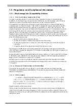
Page 14: ...between the equipment and the receiver Connect the equipment to an outlet on a circuit other than the one to which the receiver is connected Consult the dealer or an experienced radio TV technician f...

Page 15: ...egion in which it is sold Peripheral Storage Devices must be UL recognized or UL listed accessory and TUV and VDE licensed Maximum power rating of any one device is 19 watts Total server configuration...

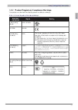
Page 16: ...USA This device complies with Part 15 of the FCC Rules Operation of this device is subject to the following two conditions 1 This device may not cause harmful interference and 2 This device must accep...

Page 17: ...E 10GbE SFP ports in a compact rack unit size The switch boasts of comprehensive network management and IP multicast functions Its fan reversible design provides system cooling to fulfill different de...

Page 18: ...scribe the LEDs on the front of the switch Base T Port LEDs 2 1 1 1 Base T Port LEDs Figure 2 2 12 11 2 1 4 3 6 5 8 7 10 9 14 13 16 15 18 17 20 19 Power Status Speed Link Activity NOTE The Speed LED i...

Page 19: ...nk Activity LED 51 NOTE is the LED indicator for the upper row ports is the LED indicator for the lower row ports SFP Port LEDs Table 2 2 LED Description Speed Green A valid link is established on the...

Page 20: ...ity Function and Management Port LEDs Table 2 3 LED Description Status Yellow System failure Power Green All DC power good Speed Orange A valid 1000Mbps network link is established Green A valid 100Mb...

Page 21: ...r setting to any supply voltage in the range from 100 240 VAC at 50 60 Hz When the PSU is connected to the power source the PSU LED lights green Power Supply LEDs Table 2 4 LED Description Power Suppl...

Page 22: ...describes the following topics Unpack the Hardware Install the Switch Connect to Power Check the Installation Connect Equipment Connect to Console Port Connect to Management Port Chapter 3 Hardware I...

Page 23: ...The switch can be installed in the following ways Flat surface installation Placed as a standalone unit on a flat surface Rack mounted installation Installed in a standard rack Installation and Safet...

Page 24: ...ver Install the Switch 3 2 2 Install in a Rack 3 2 2 1 You can install the switch in most standard 19 inch 48 3 cm racks Without Rail Installation Align the built in mounting ear to the rack holes and...

Page 25: ...20 ENGLISH Hardware Installation Pull out the internal rail 3 Pull Out Rack Rail Figure 3 4 Align the brackets to the rail holes and secure them with screws 4 Install Switch on Rail Figure 3 5...

Page 26: ...ower LED lights green Check the Installation 3 4 Check the following pointers to inspect the installation Is the switch securely installed and stable Is Are the AC power cord s properly connected to t...

Page 27: ...your dealer to purchase SFP Port 3 5 2 The switch has 4 dual speed 1GbE 10GbE SFP ports The Small Form Factor Pluggable Plus SFP port is the second generation of the SFP interconnect system designed f...

Page 28: ...llowing Slide the SFP module into an SFP port 1 Connect SFP Module Figure 3 9 Push completely until the module locks into place 2 Repeat the above procedures to install additional SFP modules 3 The SF...

Page 29: ...fication table RJ 45 Port of Switch DB9 Female Port of PC Abbreviation Description 3 2 RD Received Data 6 3 TD Transmit Data 1 8 CTS Clear To Send 8 7 RTS Request To Send 5 5 GND Ground To connect to...

Page 30: ...in 10Mbps 100Mbps or 1000Mbps Telnet SNMP and Web browser utility can all go through this port for local or remote management after the IP address subnet mask and default gateway are properly configu...

Page 31: ...This chapter describes the following topics Initial Configuration Process Configure the IP Address Manage the Switch Upgrade the Firmware Manually Install Vendor OS Chapter 4 Initial Configuration...

Page 32: ...t time configuration it is recommended to set the IP address manually Set IP Address Manually 4 2 1 To set the IP address of the switch manually perform the following Connect the switch to a computer...

Page 33: ...2 Switch Switch Switch Switch Switch From this point the IP address subnet mask and gateway of the switch has been set On the 7 command prompt input exit to go back one level The prompt changes to Sw...

Page 34: ...nitor network elements The switch supports SNMP version 1 0 2 0 and 3 0 The basic components and functions of SNMP are as follows A Managed Device in this case the switch An SNMP Agent SNMP Manager Ma...

Page 35: ...are to upgrading Initialization Stage 4 4 1 Connect the TFTP server to the switch via the management port 1 Set the service port IP address using the following commands 2 Connect the console cable to...

Page 36: ...supports two images active and backup Input the following command to download the 1 image to backup image copy tftp server ip addr file name image backup Backup Image Screen Sample Figure 4 5 Input th...

Page 37: ...ally perform the following Locate the specific QUANTA ONIE installer image that you want to download 1 For example the installer file name ly3 onie installer 1 5 3 Place the installer file into your l...

Page 38: ...rify IP Address Setting Screen Figure 4 10 In ONIE Linux shell use the 4 install_url command to update the vendor OS code Use one of the following commands install_url tftp 192 168 2 153 ly3 onie inst...

Page 39: ...This chapter tabulates the common problems and solutions that you may encounter when using the switch and provides customer service information Chapter 5 Troubleshooting...

Page 40: ...ed length and specification Check for a defective cable port module PSU 1 PSU 2 LED is in Yellow state Possible issues Fan Lock 15 sec OTP Over Temperature Process OCP Over Current Process OVP Over Vo...

Page 41: ...s can be replaced without the use of special tools Before replacing any of the PSUs verify the status of the PSU to determine if there is a need for replacement Remove the Power Supply Unit 5 2 1 Disc...

Page 42: ...ide the PSU or Hot swappable Fan module Do not disassemble any part of the PSU or Hot swappable Fan module Doing so voids the warranty and regulatory certifications For maintenance services not mentio...

Reviews: