background image

4

  Network Switch Installation Guide

SAFETY & REGULATORY INFORMATION

•  Do not push any objects into the opening of the equipment. Doing so may short internal 

components and cause fire or electric shock.

•  Use the system only with approved equipment.
•  Allow the product to cool before removing any peripherals.
•  Operate the equipment only from the type of external power source indicated on the electrical 

ratings label. If you are unsure of the type of power source required, consult your local power 

company.

•  Use only approved power cable(s).
•  To help prevent electric shock, plug the system and peripheral power cables into properly 

grounded electrical outlets. Do not use adapter plugs or remove the grounding prong from 

a cable. If you must use an extension cable, use an extension cable with properly grounded 

plugs.

•  Observe extension cable and power strip ratings. Ensure that the total ampere rating of all 

products plugged into the extension cable or power strip does not exceed 80% of the ampere 

ratings limit for the extension cable or power strip.

•  To protect the equipment from sudden, transient increase or decrease in electrical power, use 

a surge suppressor, line conditioner, or uninterruptible power supply (UPS).

•  Do not modify power cables or plugs. Consult a licensed electrician or your power company 

for site modifications. Always follow your local/national wiring rules.

•  To avoid possible damage to the system board, wait 5 seconds after turning off the system 

before removing a component from the system board or disconnecting a peripheral device.

•  When connecting or disconnecting power to the hot-pluggable power supply units, observe 

the following guidelines:


√ Unplug the power cable before removing the power supply.


√ Install the power supply to the system before connecting the power cable to the power 

supply.


√ If the system has multiple sources of power, disconnect power from the system by 

unplugging all power cables from the power supplies.

•  When disconnecting a cable, pull on its connector or on its strain-relief loop, and not on the 

cable itself.

Installation Assembly Safety Instructions

•  The power supply in this product contains no user-serviceable parts. Refer servicing only to 

qualified personnel.

•  Do not attempt to modify or use the supplied AC power cord if it is not the exact type 

required. A product with more than one power supply will have a separate AC power cord for 

each supply.

•  To remove the AC power from the system, you must unplug each AC power cord from the wall 

outlet or power supply. The power cord(s) is considered the disconnect device to the main (AC) 

power. The socket outlet that the system plugs into shall be installed near the equipment and 

shall be easily accessible.

•  A microprocessor and heat sink may be hot if the system has been running. Also, there may 

be sharp pins and edges on some board and chassis parts. Contact should be made with care. 

Consider wearing protective gloves.

•  Danger of explosion if the battery is incorrectly replaced. Replace only with the same or 

equivalent type recommended by the equipment manufacturer. Dispose of used batteries 

according to manufacturer’s instructions.

•  The system is safety certified as rack-mounted equipment for use in a server room or 

computer room, using the customer rack kit. The rail racks are designed to carry only the 

weight of the system. Do not place additional load onto any rail-mounted equipment. System 

rack kits are intended to be installed in a rack by trained service technicians.

Summary of Contents for QuantaMesh T4000 Series

Page 1: ...QuantaMesh Network Switch Installation Guide...

Page 2: ...uter rooms and similar commercial type locations The suitability of this product for other product categories and environments such as medical industrial residential alarm systems and test equipment o...

Page 3: ...ble or plug is damaged The equipment has been exposed to water The equipment has been dropped or damaged The equipment does not operate correctly when you follow the operating instructions Do not spil...

Page 4: ...e following guidelines Unplug the power cable before removing the power supply Install the power supply to the system before connecting the power cable to the power supply If the system has multiple s...

Page 5: ...or equipment damage Conform to local occupational health and safety requirements when moving and lifting equipment Use mechanical assistance or other suitable assistance when moving and lifting the eq...

Page 6: ...fety instructions apply whenever accessing the inside of the product Turn off all peripheral devices connected to this product Disconnect the AC power by unplugging all AC power cords from the system...

Page 7: ...operation of the equipment is not compromised Mechanical Loading Mounting of the equipment in the rack should be such that a hazardous condition is not achieved due to uneven mechanical loading Circui...

Page 8: ...not occur in a particular installation If this equipment does cause harmful interference to radio or television reception which can be determined by turning the equipment off and on the user is encou...

Page 9: ...or UL listed Any add in card containing modem telecommunication circuitry must be UL listed In addition the modem must have the appropriate telecommunications safety and EMC approvals for the region...

Page 10: ...omplies with Part 15 of the FCC Rules Operation of this device is subject to the following two conditions 1 This device may not cause harmful interference and 2 This device must accept any interferenc...

Page 11: ...rt Connection 24 Fan Tray of T7032 IX1 IX1B 25 Power Supply of T7032 IX1 IX1B 26 BMC of T7032 IX1B 27 Airflow Direction 28 Hardware Installation 29 Unpacking the Hardware 29 Package Contents 29 Instal...

Page 12: ...8 19 20 19 20 21 22 21 22 23 24 23 24 15 16 15 16 13 14 13 14 29 30 29 30 31 32 31 32 33 34 33 34 35 36 35 36 27 28 27 28 25 26 25 26 41 42 41 42 43 44 43 44 45 46 45 46 47 48 47 48 39 40 39 40 37 38...

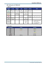
Page 13: ...Fans Working Good 100M left LED Powering On Amber Booting On Going 1G left LED Red Fan Failed Powering Failed Switch System Fault Off Powering Failed 10M left LED Blinking Activity right LED Slow Bli...

Page 14: ...28 QSFP28 port to servers and other Ethernet switches For more information on obtaining the appropriate SFP28 QSFP28 modules refer to Supported Cables and Transceivers on page 15 One management port e...

Page 15: ...4 SFP 100G Direct Attach Cooper DAC cable QSFP28 to QSFP28 100G DAC fan out cable to 4 x 25G QSFP28 to SFP28 100G Active Optical Cable AOC QSFP28 to QSFP28 5m 10G Direct Attach Cooper DAC cable SFP t...

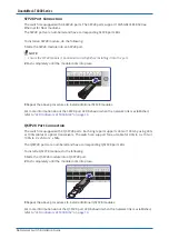
Page 16: ...shed refer to LED Indicators of T4048 IX2 on page 13 QSFP28 Port Connection The switch is equipped with 8 QSFP28 ports Each single port supports 40G or 100G by using 40G or 100G cables or optical tran...

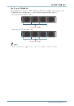
Page 17: ...le fan modules Each fan module handle is color coded to indicate its airflow direction Red indicates front to back airflow PSU2 PSU1 AC DC FAN4 FAN3 FAN2 AC DC FAN1 Fan module handles Blue indicates b...

Page 18: ...retainer The AC power connector is a standard three pronged connector The switch automatically adjusts its power setting to any supply voltage in the range from 100 240 VAC at 50 60 Hz NOTE Verify th...

Page 19: ...switch and BMC The system administrator can manage BMC remotely via Web by entering the its default IP address By default the BMC IP address is pre configured to 192 168 0 120 BMC default IP address...

Page 20: ...is CAUTION Front to Back Airflow The air intake is located on the front panel of the switch The cool air is sucked in from outside the chassis and pushed toward the rear of the chassis The hot air exh...

Page 21: ...91 95 92 190 96 192 15 16 13 81 14 85 82 185 86 187 83 87 84 186 88 188 13 14 11 73 12 77 74 181 78 183 75 79 76 182 80 184 11 12 17 97 18 101 98 193 102 195 99 103 100 194 104 196 17 18 23 121 24 12...

Page 22: ...Fans Working Good 100M left LED Powering On Orange Booting On Going 1G left LED Red Fan Failed Powering Failed Blue Show BMC ID Off Powering Failed Booting Failed 10M left LED Blinking Activity right...

Page 23: ...ervers and other Ethernet switches For more information on obtaining the appropriate QSFP or QSFP28 modules refer to Supported Cables and Transceivers on page 24 One management port enables you to man...

Page 24: ...o QSFP28 100G DAC fan out cable to 4 x 25G QSFP28 to SFP28 100G Active Optical Cable AOC QSFP28 to QSFP28 5m 40G Direct Attach Copper DAC cable QSFP to QSFP 40G DAC fan out cable to 4 x 10G QSFP to 4...

Page 25: ...0 224 31 32 29 145 30 149 146 217 150 219 147 151 148 218 152 220 29 30 27 137 28 141 138 213 142 215 139 143 140 214 144 216 27 28 3 Repeat the above procedures to install additional QSFP28 modules F...

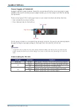
Page 26: ...Plug retainer The AC power connector is a standard three pronged connector The switch automatically adjusts its power setting to any supply voltage in the range from 100 240 VAC at 50 60 Hz NOTE Verif...

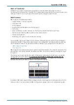
Page 27: ...plays the role of monitoring the whole system The BMC is an independent subsystem with its own processor and memory so that it can run well even if the switch system hangs or powers down BMC Features...

Page 28: ...is CAUTION Front to Back Airflow The air intake is located on the front panel of the switch The cool air is sucked in from outside the chassis and pushed toward the rear of the chassis The hot air exh...

Page 29: ...ge before starting the installation 1 Place the box on a flat and stable surface and cut the straps securing the box 2 Carefully remove the switch Then place it on a flat and clean surface 3 Remove al...

Page 30: ...nlet module See Front to Back Airflow on page 28 Blue indicates back to front airflow air outlet module See Back to Front Airflow on page 28 To ensure proper airflow make sure that when you install th...

Page 31: ...steps to remove another inner rail 2 Install the inner rails on the switch Align the hooks on the switch and the holes in the inner rail and then slide the inner rail backward until it is locked into...

Page 32: ...ail by aligning the hooks with the front rack holes b Then release the latch to lock the hooks into place a b 5 Mount the switch into the rack Pull the middle rail out until it is fully extended ensur...

Page 33: ...onsole port you can perform the following Configure the switch using the CLI commands Manage and monitor network activity by Command Line Interface CLI management Manage and monitor network activity b...

Page 34: ...ault gateway are properly configured To avoid an IP address conflict make sure to complete the initial configuration see Connecting to the Console Port on page 33 before connecting the management port...

Page 35: ...least one power supply must connect to a power source To connect the switch to a power source do the following 1 Connect one end of the AC power cord to an AC power connector PSU2 FAN4 FAN3 FAN2 FAN1...

Page 36: ...power indicator does not turn on when the power cord is plugged in you may have a problem with the power outlet power cord or power supply However if the unit powers off after running for a while che...

Page 37: ...n replace the defective unit without powering down the system provided that there is at least one power supply must connect to a power source To replace the power supply unit do the following T4048 IX...

Page 38: ...from the chassis PSU2 AC DC FAN4 FAN3 NOTE Take note of the part number of the removed PSU When making order for replacement modules make sure that the part number of the new PSU is the same as the pa...

Page 39: ...the chassis FAN4 FAN3 FAN2 FAN1 AC DC AC DC T4048 IX2 FAN4 FAN3 FAN2 AC DC FAN1 T7032 IX1 IX1B NOTE Take note of the part number of the removed fan module When making order for replacement modules ma...

Page 40: ...of different protocols i e FTP TFTP and HTTP to download the installer file from your local server To download and update the vendor OS code manually perform the following 1 Locate the specific QUANT...

Page 41: ...t 4 In ONIE Linux shell use the install_url command to update the vendor OS code Use one of the following commands install_url tftp 192 168 2 153 ly3 onie installer 1 5 3 or install_url ftp 192 168 2...

Reviews: