


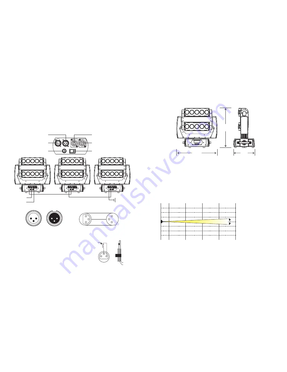
(LUX)
R
G
B
W
9880
20070
28680
32880
1180
1970
2240
3140
705
840
1040
1410
420
490
610
1070
0m
5
°
1m
3m
5
m
7
m
.04.
04. PHOTOMETRIC DATA
DIMENSION
480
260
480
DMX Output
3-Pin XLR Socket
DMX Input
3-Pin XLR Socket
1:Ground
2:Data(-)
3:Data(+)
1
2
3
1
2
3
1
2
3
1
2
3
COMMON
DMX+
DMX-
DMX512 IN
3-PIN XLR
DMX512 OUT
3-PIN XLR
.07.
Connect the provided XLR cable to the female 3-pin XLR output of your controller and the
other side to the male 3-pin XLR input of the moving head. You can chain multiple
Moving head together through serial linking. The cable needed should be two core,
screened cable with XLR input and output connectors. Please refer to the diagram below.
DMX-512 connection with DMX terminator
For installations where the DMX cable has to run a long
distance or is in an electrically noisy environment, such as
in a discotheque, it is recommended to use a DMX
terminator. This helps in preventing corruption of the digital
control signal by electrical noise. The DMX terminator is
simply an XLR plug with a 120 Ω resistor connected
between pins 2 and 3,which is then plugged into the output
XLR socket of the last fixture in the chain. Please see
illustrations below.
1
2
3
PIN3
PIN2
120
Ω
07. DMX-512 CONTROL CONNECTIONS
POWER IN
POWER OUT
Power Switch
DMX IN
DMX OUT
Fuse
POWER IN
DMX IN


