INSTRUCTION MANUAL
QA-TEMP
IN
S
T
R
U
C
T
IO
N
M
AN
U
AL
Q
A
-T
E
M
P
2
09
2015
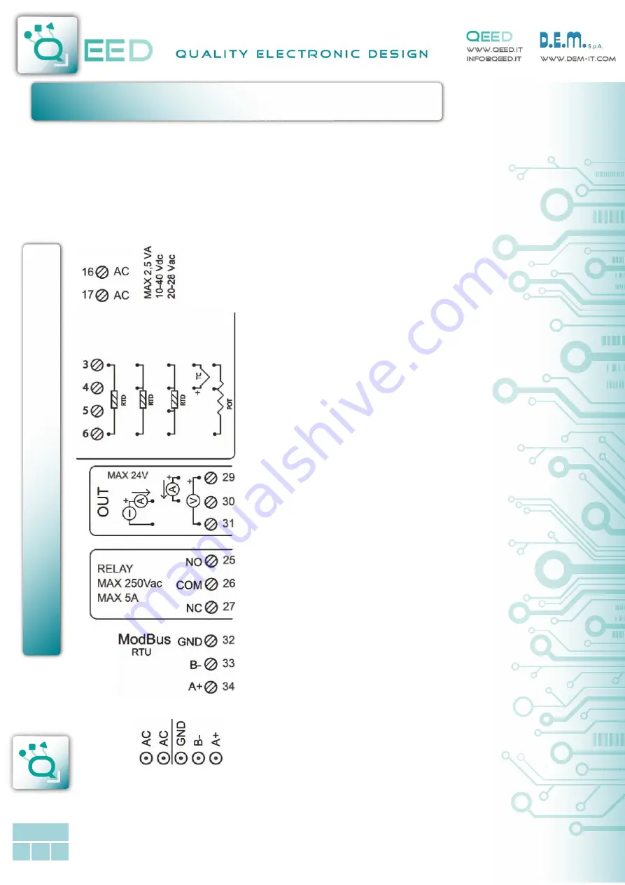
ELECTRICAL CONNECTIONS
:
DESCRIPTION:
The QA-TEMP is an Universal Temperature Converter, 4-ways isolated, with one analog input (temperature,
potentiometer, resistance) and three different outputs. The module has a programmable analog output (voltage or
current), one digital output (5A SPDT relay) and one serial RS485 slave output. Thanks to the presence of the RS485 serial
port, the device can perform advanced functions such as I / O Module with Modbus RTU protocol. The QA-TEMP behaves
as a slave device by placing n°1 RTD/ TC input , n°1 AO, n°1 DO.
POWER SUPPLY:
10...40 Vdc or 20...28 Vac - Connectors 16 and 17, or by T-BUS
connector (optional tool) on the base of the module (see the
picture placed on the bottom of this page).
ANALOG INPUT TEMPERATURE SENSORS CONNECTION:
Depending on the type of sensor or signal available, make the
connection as shown. For example, to connect a 3-wire RTD
sensor requires a connection to terminals 3, 4 and 6. The Thermo-
couple, whatever it is, it requires the connection between termi-
nals 3 and 4.
To connect a potentiometer use terminals 3, 4 and 6.
To make resistance measurements at 2, 3 and 4 wires to follow
the wiring diagram for the RTD.
ANALOG OUTPUT:
For the voltage analog output, connect terminals 31 and 29
(positive).
For the ACTIVE current analog output, connect terminals 29
(positive) and 30.
For the PASSIVE current analog output, connect terminals 30
(positive) and 31.
Analog output supply: 13 Vdc, max 30mA.
DIGITAL OUTPUT:
SPDT Relay Output. Connect the terminals 25 Normally Open and
27 Normally Closed. The default setting is Normally Open (NO).
SERIAL OUTPUT RS485 Modbus RTU:
Available on terminals 32 GND, 33 (B-), 34 (A+), or by using T-BUS
connector to be mounted on the base of the module. To configure
the device use the software FACILE QA-TEMP or by direct
connection via RS485 using the Modbus register map shown in
this manual.
T-BUS CONNECTION
(T-BUS connector required):
It is possible to mount the accessory T-BUS to carry both power
and serial communication. The number of modules supported by
the function of the power supply bus is used (check the absorption
of the modules).
ENGLISH


