5
1.1 Introduction
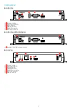
This manual explains how to install and configure your DMB 400 device.
Recommendations and warnings
This device is designed to be used indoor.
This device is intended to work with the power supply unit. This power supply unit must be connected to a mains socket conforming to standard NF C
15-100. If the AC power cable is damaged, it must be replaced. It is possible to order a power supply unit replacement by sending a request to the
email address
.
This device is a Class A device. In a residential environment, this device may cause radio interference. In this case, the user is asked to take
appropriate measures.
Content of the package
Items
Description
Q uantity
Device
DMB 400 device with Gekkota embedded.
1
Power supply unit
12 V power supply unit with cable of 1.2 m.
1
Labels
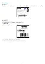
One on the cardboard packaging and another one at the back of the product.
Additional label can be present in case build-in options.
2
WLAN antennas
To be screwed on the dedicated WLAN locations.
Provided with the device when it is supporting the
W L AN
option.
2
Summary of Contents for 4.13.15 002E
Page 1: ...U ser manual DMB 400 4 13 15 002E...
Page 4: ...4 Part I Description and installation...
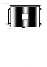
Page 7: ...7 1 2 1 Device xture...
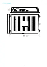
Page 8: ...8 1 2 2 Device dimensions...
Page 15: ...15 N Function 1 CD 2 RX D 3 TX D 4 DTR 5 GND 6 DSR 7 RTS 8 CTS 9...
Page 17: ...17...
Page 19: ...19 Part II Applicative user interface...
Page 21: ...21 Part III Administration console user interface...
Page 49: ...49 Part IV Con guration b y script...
Page 51: ...51 Part V Technical information...
Page 55: ...55 Part VI Contacts...
Page 57: ...57 Part VII Appendix...
Page 62: ...62 15 16 17...


