Summary of Contents for 691

Page 1: ...www SteamPoweredRadio Com I I I I I I I I I I I I I I I I I I I QEI MODEL 691 MODULATION MONITOR ...

Page 2: ... and Monitor Outputs are located on the rear panel 1 2 ELECTRICAL SPECIFICATIONS RF Frequency Range 88 1 107 9MHz Thumbwheel selected RF Input to g arantee 66dB S N in a 30KHz Bandwidth Ant 3mv to 200mv Sig Sample 2mw to 50W depending on external load Total Modulation Display Modulation Meter Accuracy 2 entire range Frequency Response 0 2dB 30Hz 75KHz Range 0 133 20dB to 2dB Ballistics per FCC reg...

Page 3: ...A Inj narrow 7 SCA Inj wide Distortion Left or Right Right Sub Phase Cai Gen Phase AM S N Main SCA Mod THO 0 05 IMD 0 1 SMPTE SCA 4KHz dev 1 50H z to 5KHz 150us de emp Outputs Left 10 dbm bal a d Hi z Right 10 dbmbal and Hi z Scope 1V8p Frequency X I F Pilot SCA TTL Spectrum Analyzer Output 70db 120KHz or 400K Hz X horix 4V p Y vert 0 5V 10db 1 3 MECHANICAL SPECIFICATIONS Dimensions lO H X 1911 WX...

Page 4: ...ted on the rear panel All correspondence to your sales representative or the factory in regard to the unit should reference the complete Model and Serial Numbers 1 5 OPTIONS 01 SCA Monitor option 67KHz consists of the plug in board assenbly A6 02 SCA Monitor option special frequency not FCC Type Approved 03 CCIR Specifications not FCC Type Approved ...

Page 5: ...rature below the maximum specified 50 C Mount the unit to the rack using 10 countersink screws and finishing washers The unit requires a 105 125V single phase 50 60Hz power source or a 120 250V single phase 50 60Hz power source The identification plate on the back panel shows for which power source the unit is wired See Section 5 7 for information on changing taps 2 3 MONITOR coNNECTIONS 1 Connect...

Page 6: ...Before returning a unit for repair or cal ibration contact the factory or your authorized representative for Return Authorization Attach a tag showing owner s name and address A description of the service required should also be included Unit must be shipped prepaid and insured for full val ue USE THE ORIGINAL SHIPPING CARTON AND PACKING MATERIAL FOR RE SHIPMENT ...

Page 7: ...input mixer is being protected by an input clipper 5 MUTE Switch A1S3 a With MUTE switch in ON position unit wil1 mute all signals below RF LEVEL OK threshold 6 COMP Jack AlJl provides a 6Vpp wideband composite signal 7 DE EMP AUDIO Jack A1J2 provides a 6Vpp 400Hz signal with 75usec de emphasis NOTE This signal is NOT filtered to remove 19KHz 8 TOTAL MODULATION Displays Yellow a Meter AlMl in conj...

Page 8: ...d 0ADJ AlRl indicate the presence of the 19KHz pilot tone and provide monitor phase calibration in conjunction with 0 CAL position of CHANNEL B DISPLAY SELECT Pilot 0 ADJ AlRl is set for a null on CHANNEL B meter This adjustment is accurate even with modu lation applied 11 SCA PRESENT indicator A1DS4 indicates the presence of SCA The DEV switch A1S9 may be set to cause CHAN EL B SCA MOD display to...

Page 9: ...RANGE dB readouts A1DS5A and AlDSSB provide two metering displays with a range of Oto 133 with FCC ballistics MOD position or 70d8 to 3dB with semi VU ballistics AUTO or HOLD position These displays may be switched to or indications and may be deemphasized by pushbuttons A2Sl5A or A1S15B NOTE FM and AM S N are automatically deemphasized c PEAK thumbwhee1s AlS12A and A1S12B and 1eds AlCR6A and AlCR...

Page 10: ... modulation w ith the MOD METER POS or NEG pushbuttons NOTE The Total Peak Mod Flasher and Total Modulation Meter will only agree if the transmitter is modulated by a low distor tion si ne wave Any distortion w ill cause positive to nega tive assynmetry approximately double the amount of the dis tortion in percent Remember thet the flasher reads the highest polarity and that the meter reads the se...

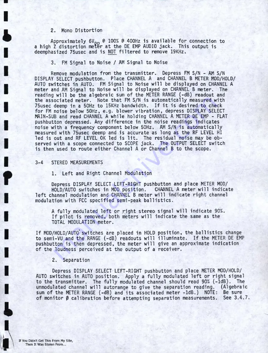
Page 11: ...t The residual noise may be ob served with a scope connected to SCOPE jack The OUTPUT SELECT switch is then used to route either Channel A or Channel B to the scope 3 4 STEREO MEASUREMENTS 1 Left and Right Channel Modulation Depress DISPLAY SELECT LEFT RIGHT pushbutton and place METER MOD HOLD AUTO s titches in MOD position CHANNEL A meter will indicate left channel modulation and CHANNEL B meter ...

Page 12: ...in AUTO position A fully modulated L R or L R signal will indicate 90 ldB on its respective meter The other meter will autorange to give the crosstalk reading Algebraic sum of METER RANGE dB and its associated meter ldB 7 Pilot Injection and Monitor Phase Calibration Depress DISPLAY SELECT PILOT 0 CAL pushbutton and place METER MOD HOLD AUTO switches in MOD position Pilot injection is then read on...

Page 13: ...ushbutton and place METER MOD HOLD AUTO switches in MOD position CHANNEL A meter will read SCA Injection on the PILOT scale through a wide filter This filter allows in jection to be monitored while modulating the SCA 3 SCA Modulation Set monitor up as in 3 5 2 above Place SCA DEV switch in 4KHz or 6KHz position as desired This sets the deviation for 100 CHANNEL B meter will indicate SCA Modulation...

Page 14: ...lator is also fed to the A4 assembly producing a 10 7MHz IF The L O phase lock loop circuitry is located on the A2 assembly The 10 7MHz IF is filtered demodulated and the resulting composite signal is amplified and fed to the various filtering stereo and SCA demodulation and metering circuitry required A portion of the 10 7MHz IF is also fed to a mixer along with a swept 2nd L O operating at 10 25...

Page 15: ...e 100 PEAKS PER MINUTE display Channel A designators are i n units Channel B designators are in hundreds Al and Ul along with their associated PEAK thumbwheel are used to drive the TEST DISPLAY PEAK led Signal components sslected by the DISPLAY SELECT push buttons and the METER switch are amplified or inverted by U2 and fed to a combination attenuator amplifier This combination provides gain in lO...

Page 16: ... also used to sweep the 1st L O in SPECTRUM ANALYZER WIDE mode through Ql5 The 455KHz output of mixer 22 is fed through buffer Q17 and Ql8 to the spectrum analyzer filter and logarithmic ampl ifier U4 and associated circuitry The output of the log amp is AM demodulated and fed through active filter U5 to the SCOPE VERT jack and the AM Noise measurement circuit 5 AS Stereo Demodulator Assembly Comp...

Page 17: ...idth to allow injection measurements under modulation and also to prevent unwanted composite signal components from reaching the SCA demodulator U2 is a phase locked loop demodulator The audio output is buffered by Q6 filtered and amplified by Ul and U4 Q 3 changes the 100 deviation point from 4KHz to 6KHz depending upon the front panel SCA DEV switch U3 detennines SCA presence and also drives the...

Page 18: ...lignment of this unit verify that the three supply voltages are present and correct 5 2 PLL AND TOTAL METER ALIGNMENT A2 Assembly 1 2 Place MOD PEAK Thumbwheel AISS to 100 Measure voltage at A2U17 6 TPl this voltage should be 3 00V 15V 3 Measure voltage at A2U18 6 TP2 Adjust A2R69 until this voltage has the s me magnitude but opposite polarity of step 5 2 2 3 00V 15V 4 Measure voltage on center ar...

Page 19: ...y is exactly a 000000 MHz NOTE This will set the L O exactly 10 7 MHz above the indication on the CARRIER FREQ thumbwheel A1S2 NOTE The crystal used in the 691 Modulation Monitor is a high a0curacy crystal with stability of 2 5 PPM from 0 60 C 5 3 DUAL AVERAGE VOLTMETER ALIGNMENT A3 Assembly 1 Calibrate PLL and Total Meter Section 5 2 2 Preliminary set up a Place thumbwheels AlS12A and A1S12B to 1...

Page 20: ... B meter AlM2B reads 100 16 Plade switch A1S13B in position 17 Adjust A3R125 until C H B meter A1M2B reads 100 18 Pl ace MOD HOLD AUTO switch A1Sl4B i n AUTO position 19 Repeat step 12 of this section Adjust A3R160 for auto range set point 20 Set input frequency to exactly 38000 Hz Adjust input l evel until M O D PEAK light AlDSl just l ights 21 Depress 38K GEN0 button on DISPLAY SELECT switch AlS...

Page 21: ... the complex waveshape of a stereo signal the TOTAL MOD meter AlMl will not read 100 ith a left or right only signal tfieTOTAL MOD meter will read about 96 Set up monitor for stereo separation measurements Section 3 4 1 and 2 Adjust LEFT filter control A1R8 until CH A meter AlM2A reads 90 Generate a signal i n the right channel of the stereo generator exactly 40 dB below the signal in the left cha...

Page 22: ...t A6R33 until signal on A6U2 9 locks onto incoming 67 KHz 9 Reduce SCA injection to 3 Adjust A6R39 until SCA PRESENT lamp A1DS4 just lights r 10 Connect your SCA generator to the COMP IN A1J13 Adjust COMP LEVEL A1R4 for 10 injectiori 11 Depress SCA INJ NARRm MAIN button on DISPLAY SELECT switch AlSll Place DEV switch AlS9 in 4 KHz position 12 Modulate the SCA generator with a frequency of 1660 Hz ...

Page 23: ...the CARRIER FREQUEN CY thumbwheel AlS2 Modulate the Signal Generator with a 120 KHz tone at approximately 75 KHz deviation j Adjust A4R97 until the 120 KHz sideband appear near the edge of the scope displ ay k Adjust A4C30 to peak Spectrum Analyzer display 1 Depress WIDE button on switch A1S4B Increase modulating frequency to about 300 KHz Adjust A4R114 and A4Rll0 if necessary until 300 KHz sideba...

Page 24: ... steps c and d if necessary i Depress CAL button A S7 Adjust A4L17 until carrier of calibrate oscillator appears centered on the Spectrum Analyzer display j Adjust A4R35 and A4Ll6 until the carrier is in its deepest null This will be a modulation percentage of 102 7 NOTE Due to some distortion when filtering a square wave some positive to negative assymetry will be noted ...

Page 25: ...www SteamPoweredRadio Com I I I I I I I I r SECTION 6 PARTS LIST I I I I I I I I I ...

Page 26: ...LED Red AlCR4 Diode LED Yellow AlCRS Diode LED Green AlCR6A A1CR6B Diode LED Red A1CR7 Diode Bridge Rect A1CR8 Diode Bridge Rect AlDSl Amber Lens A1DS2 Display LED Part of A9 Ass y AlDS3 Green Lens AlDS4 Blue Lens AlDSSA AlOS5B Display LED Part of Al0 Ass y AlFl Fuse 1 Amp AlFLl Filter Left Right AlFL2 Filter L R 38KHz AlFL3 Filter L R Indicates factory selected nominal value shown QEI Part No 110...

Page 27: ...100 Ohm 2W Res Var lOK 2W Res Var SK 2W Res Carb 4 7K W 5 Res Carb lOK W 5 Res Var 250 Ohm Res Var 250 Ohm Res Carb 2 2K W 5 Res Carb 2 2K W 5 Res Carb 1 2K W 5 Res Carb 620 Ohm W 5 Res Var 250 Ohm Res Var 250 Ohm J Res Var 250 Ohm Res Carb 390 Ohm W 5 Res Carb 390 Ohm W 5 Res Carb 330 Ohm W 5 Res Neg Temp Coefficient Res Neg Temp Coefficient Res Neg Temp Coefficient Res Carb 620 Ohm W 5 Res Carb ...

Page 28: ...l Switch 3 pos on off Mom Switch P B Momentary Switch DPDT Switch SPOT Switch DPDT Switch Part of All Ass y Switch Thumbwheel Switch DPDT Switch 3 pos on off on Switch P B Momentary Switch SPOT Transformer Power Transformer Audio Transformer Audio IC 5 Volt Reg IC 12 Volt Reg IC 12 Volt Reg Lamp Socket Lamp Socket Lamp Socket Fuse Holder QEI Part No 175 0012 F 175 0010 175 0012 F 175 0010 175 0013...

Page 29: ...f Cap Mica 470pf Cap Mica lOOOpf Cap Mica 27pf Cap Var 1 lOpf Cap Mica 470pf Cap Mica 470pf Cap Cer luf Cap Cer OOluf Cap Tant 22uf Cap Elect 5uf Cap Elect lOOuf Cap Tant 22uf Cap Elect 5uf Cap Elect lOOuf Cap Mica 250pf Cap Mica 15pf Cap Tant 47uf Cap Tant 2 2uf Cap Cer Oluf Cap Elect 5uf Diode Silicon Diode Germanium Diode Si 1i con Indicates factory selected nominal value shown QEI Part No 6910...

Page 30: ... A2Rll Res Carb 100 Ohm W A2Rl2 Res Carb 3 3K W 5 A2R13 Res Carb 330 Ohm W A2R14 Res Carb 390 Ohm W A2Rl5 Res Carb 270 Ohm W A2Rl6 Res Carb 270 Ohm W A2Rl7 Res Carb 620 Ohm W A2R18 Res Carb 1 5 K W 5 A2Rl9 Res Carb 1 5K W 5 A2R20 Res Carb 33K W 5 A2R21 Res Carb 47K W 5 A2R22 Res Carb 56K W 5 A2R23 Res Carb 150K W 5 A2R24 Res Carb 33K W 5 A2R25 Res Carb 33K W 5 Indicates factory selected nominal va...

Page 31: ...lOK W 5 RC20GF103J I A2R46 Res Carb 33K W 5 RC20GF333J A2R47 Res Carb 330 Ohm W 5 RC20GF331J A2R48 Res Carb 120 Ohm W 5 R 20GF121J A2R49 Res Carb 470 Ohm W 5 RC20GF471J I A2RSO Res Ca rb 1 SK W 5 RC20GF152J A2RS1 Res Carb 4 7K W 5 RC20GF472J A2RS2 Res Carb 10K W 5 RC20GF103J I A2R53 Res Carb 4 7K W 5 RC20GF472J A2R54 Res Carb lSK W 5 RC20GF153J A2RSS Res Carb 33K W 5 RC20GF333J I A2R56 Res Carb 4 ...

Page 32: ...06J A2R92 Res Carb 3 3K W 5 RC20GF332J I A2R93 Res Carb 3 3K W 5 RC20GF332J A2R94 Res Carb 4 7K W 5 RC07GF472J A2R95 Res Carb 15K W 5 RC20GF153J I A2R96 Res Carb 1K W 5 RC20GF102J A2R97 Res Carb 7 5K W 5 RC20GF752J A2R98 Res Film 7 5K W 5 165 7501 A2R99 Res Var lK 167 3001 I A2Rl00 Res Film 1 2 1K W 1 167 1211 A2R101 Res Carb l0K W 5 RC20GF103J A2R102 Res Carh 8 2K W 5 RC20GF822J I A2R103 Res Film...

Page 33: ...Counter IC Up Down Counter IC Flip Flop IC Decade Counter IC Decade Counter IC Binary Counter IC Decade Counter IC Retriggerable One Shot IC Op Amp IC Op Amp IC Op Amp IC Op Amp IC Op Amp IC Op Amp IC One Shot IC Quad Comparator IC One Shot IC Quad NOR Gate IC Quad NANO Gate IC Decade Counter IC Quad NAND Gate IC Dual NAND Gate Crystal 8 0 MHz QEI Part No RC07GF472J RC20GF472J RC20GF272J 18 0 2213...

Page 34: ...W 5 RC20GF103J I A3R79 A3R179 Res Carb 560K W 5 RC20GF564J A3R80 A3R180 Res Carb lOOK W 5 RC20GF104J A3R81 A3R181 Res Carb lOOK W 5 RC20GF104J I A3R82 A3R182 Res Carb 100K W 5 RC20GF104J A3R83 A3R183 Res Carb lOOK W 5 RC20GF104J A3R84 A3Rl84 Res Carb 1K W 5 RC07GF102J A3R85 A3R185 Res Carb 270 Ohm W 5 RC07GF271J I A3R86 A3Rl86 Res Carb 270 Ohm W 5 RC07GF271J A3R87 A3R187 Res Carb 270 Ohm W 5 RC07G...

Page 35: ...Res Carb 12K W 5 Res Carb 3 3K W 5 Res Carb 3 3K W s Res Carb 12K W 5 Transistor NPN Transistor NPN Transis t or NPN Transistor NPN Transistor PNP Transistor NPN Transistor NPN Transistor NPN Transistor NPN Transistor NPN IC Quad Comparator IC Op Amp IC Hex Inverter IC Decoder Driver IC Quad NANO Gate IC Counter Up Down IC Quad NOR Gate IC Quad Comparator IC Op Amp IC Timer IC Timer IC Dual NANO G...

Page 36: ...f Cap Elect lOOuf Cap Elect lOOuf Cap Elect 50uf Cap Elect 15uf Cap Elect 15uf Cap Elect 50uf Cap Tant luf Cap Tant 2 2uf Cap Tant 47uf Cap Cer luf Cap Elect lOOuf Cap Elect 47uf Cap Cer luf Cap Cer OSuf Cap Cer Oluf Cap Tant 2 2uf Diode Silicon Diode Silicon Diode Silicon Diode Silicon Diode Germanium Diode Silicon Diode Silicon Diode Silicon Res Film 200K W 1 Res Film 100K W 1 Res Film 49 9K W 1...

Page 37: ...s Carb 2 2K W 5 RC20GF222J A3R32 A3R132 Res Film 23 7K W 1 165 2372 A3R33 A3R133 Res Carb lOK W 5 RC20GF103J I A3R34 A3Rl34 Res Carb lK W 5 RC20GF102J A3R35 A3R135 Res Carb 4 7K W 5 RC07GF472J A3R36 A3R136 Res Film 2 67K W 1 165 2671 I A3R37 A3Rl37 Res Film 1 21K W 1 165 1211 A3R38 A3R138 Res Carb 4 7K W 5 RC07GF472J A3R39 A3R139 Res Film 23 7K W 1 165 2372 A3R40 A3Rl40 Res Film 768 Ohm W 1 165 76...

Page 38: ... 1680 A4C21 Cap Mica 2 22pf var 110 6518 I A4C22 Cap Mica 2 22pf var 110 6518 A4C23 Cap Mica 68pf DMlS 110 1680 A4C24 Cap Mica 2 22pf var 110 6518 A4C25 Cap Mica 2 22pf var 110 6518 I A4C26 Cap Mica 2 22pf var 110 6518 A4C27 Cap Mica Slpf DM15 110 1510 A4C28 Cap Cer luf 110 0104 I A4C29 Cap Mica Sp DMlS 110 1 500 A4C30 Cap Mica 5 65pf var 110 6565 A4C31 Cap Mica 50Op f DMlS 110 1501 I A4C32 Cap Po...

Page 39: ...Cap Cer luf Cap Cer luf Cap Cer luf Cap Cer luf Cap Cer luf Cap Mica 27pf DMlS Cap Mica 27pf DMlS Cap Cer luf Cap Mica Spf DMlS Cap Cer luf Cap Cer luf Cap Cer Oluf Cap Cer OSuf Cap Mica 620pf DMlS Cap Cer luf Cap Cer OOluf Cap Tant l Ouf Cap E1e ct 20 0u f Cap Cer luf Cap Cer luf Ca p E 1e ct 20 0 u f Cap Cer luf Cap Cer Oluf Cap Poly lOOOpf Cap Poly lOOOpf Cap Cer luf Cap Mica 51pf DM15 Cap Cer ...

Page 40: ...e Silicon Diode Silicon Diode Germanium Di ode Germanium Diode Varicap Diode Varicap Diode Silicon Diode Silicon Diode SCR Diode Silicon Diode Silicon Diode Silicon Filter 1st IF Filter 2nd IF Filter 2nd IF Inductor RF Inductor RF Inductor RF toroid Inductor IF toroid Inductor IF toroid Inductor IF toroid Inductor IF toroid Inductor IF toroid Inductor IF toroid Inductor Det toroid QEI Part No 110 ...

Page 41: ...0 04401 A4Q9 Transistor NPN 160 04401 A4Ql0 Transistor PNP 160 04403 A4Qll Transistor NPN 16 0 04401 I A4Q12 Transistor PNP 160 04403 A4Q13 Transistor NPN 160 05179 A4Ql4 Transistor NPN 160 05179 I A4Q1S Transistor FET 160 13819 A4Q16 Transistor NPN 160 04401 A4Q17 Transistor NPN 160 04401 I A4Ql8 Transistor PNP 160 04403 A4Ql9 Transistor NPN 160 04401 A4Q20 Transistor NPN 160 04401 A4Q21 Transist...

Page 42: ...A4R26 Res Carb 3 3K W 5 RC20GF332J A4R27 Res Carb 3 3K W 5 RC20GF332J A4R28 Res Carb 2 2K W 5 RC20GF222J I A4R29 Res Carb 2 2K W 5 RC20GF222J A4R30 Res Carb 2 2K W 5 RC20GF222J A4R31 Res Carb 4 7K W 5 RC20GF472J A4R32 Res Carb 4 7K W 5 RC20GF472J I A4R33 Res Carb 4 7K W 5 RC20GF472J A4R34 Res Carb 3 3K W 5 RC20GF332J A4R35 Res Var lK 167 3001 I A4R36 Res Carb 1 2K W 5 RC20GF122J A4R37 Res Carb 33K...

Page 43: ...SK W 5 RC20GF153J A4R73 Res Carb 4 7K W 5 RC20GF472J I A4R74 Res Carb 4 7K W 5 RC20GF472J A4R75 Res Carb 22K W 5 RC20GF223J A4R76 Res Carb lK W 5 RC20GF102J A4R77 Res Carb 4 7K W 5 RC20GF472J I A4R78 Res Carb 12K W 5 RC20GF123J A4R79 Res Var lOK 167 3002 A4R80 Res Carb 1 SK W 5 RC20GF152J I 44R81 Res Carb lOK W 5 RC20GF103J A4R82 Res Carb 82K W 5 RC20GF823J A4R83 Res Carb 3 3K W 5 RC20GF332J I A4R...

Page 44: ...b lOK W 5 RC20GF103J I A4 R11 7 Res Carb 1K W 5 RC20GF 102J A4Rll8 Res Carb 470 ohm W 5 RC20GF471J A4Rl19 Res Carb 27K W 5 RC20GF 273J I A4Rl20 Res Carb 3 3K W 5 RC20GF 332J A4Rl21 Res Var lK 167 3001 A4R122 Res Carb 51 Ohm W 5 RC20GFS10J I A4R123 Res Carb 100 Ohm W 5 RC20GF101J A4R124 Res Carb 4 7 Ohm W 59 RC20GF4R7J A4R125 Res Carb 4 7 Ohm W 5 RC20GF4R7J A4Rl26 Res Carb 1 SK W 5 RC20GF152J I A4R...

Page 45: ...luf Cap Cer luf Cap Mica 120pf DMlS Cap Mica 120pf DMlS Cap Cer 0luf Cap Mica 470pf DMlS Cap Mica 180pf mus Cap Var S 6Spf Cap Cer luf Cap Elect Suf Cap Var S 6Spf Cap Var S 6Spf Cap Elect 200uf Cap Elect 200uf Cap Cer luf Cap Cer luf Cap Cer luf Cap Cer luf Cap Elect l00uf Cap E l ect lSuf Cap Mica 250pf DMlS Cap Mica l0pf DMlS Cap Cer luf Cap Ce r 1uf Cap Cer 0Suf Cap Tant 1 0uf I I I I I I I I ...

Page 46: ... Diode Silicon 113 04446 I ASCRl0 Diode Silicon 113 04446 ASCRll Diode Silicon 113 04446 ASCR12 Diode Silicon 113 04446 I ASCR13 Diode Silicon 113 04446 ASLl Inductor Pilot Filter 140 42160 I ASL2 Inductor Pilot Filter 140 42155 ASL3 Inductor Pilot Filter 140 42160 ASQl Transistor NPN 160 04401 I ASQ2 Transistor NPN 160 04401 ASQ3 Transistor FET 160 13819 ASQ4 Transistor FET 160 13819 I ASQS Trans...

Page 47: ...W 5 RC20GF272J ASR16 Res Carb 1 SK W 5 RC20GF152J I ASR17 Res Carb lOK W 5 RC20GF103J ASR18 Res Carb 100 Ohm W 5 RC20GF101J ASR19 Res Carb 1 SK W 5 RC20GF152J ASR20 Res Carb 68 Ohm 2W 10 RC42GF680K I ASR21 Res Carb 330 Ohm W 5 RC20GF331J ASR22 Res Carb lK W 59 6 RC20GF102J ASR23 Res Carb lK W 5 RC20GF102J I ASR24 Res Carb lOK W 5 RC20GF103J ASR25 Res Carb lOK W 5 RC20GF103J ASR26 Res Carb lOK W 5 ...

Page 48: ...RC20GF102J ASR62 Res Carb _1 2K W 5 RC20GF 122J I ASR63 Res Carb 1 2K W s 9 RC20GF122J ASR64 Res Carb 10 K W 5 RC 20GF103J ASR65 Res Carb 6 BK W 5 RC20GF 682J I ASR66 Res Carb 33K W 5 RC20GF 333J ASR67 Res Var 25K 167 3004 ASR68 Res Carb 270 Ohm W 5 RC07GF271J I ASR69 Res Carb lOK W 5 RC20GF103J ASR70 Res Carb 120K W 5 RC20GF124J ASR71 Res Carb 1 5K W 5 RC20GF152J ASR72 Res Carb 6 8K RC20GF682J I ...

Page 49: ...arb lOK W 5 Res Carb 33K W 5 Res Carb 4 7K W 5 Res Var 10K Res Carb 27K W 5 Res Var lOK Res Carb 33K W 5 Res Carb lOK W 5 Res Carb lOK W 5 Res Carb 33K W 5 Res Var lOK IC Comparator IC Op Amp IC Comparator IC PLL IC Decade Counter IC D Flip Flop IC Quad NAND Gates IC Quad NAND Gates IC D Flip Flop IC Op Amp IC Op Amp IC Op Amp IC Op Amp IC Quad NAND Gates IC Quad NOR Gates QEI Part No RC20GF682J R...

Page 50: ...00pf DM1 5 110 1301 A6C17 Cap Cer 0 l uf 110 0103 A6C18 Cap Cer 0luf 110 0103 A6C19 Cap Mica 820pf DM15 110 1821 I A6C20 Cap Cer 0luf 110 0103 A6C21 Cap Elect 5uf 110 3505 A6C22 Cap Cer 1uf 110 0104 I A6C23 Cap Tant 1 0uf 110 3105T A6C24 Cap Ce r luf 110 0104 A6C25 Cap Poly 10 000pf 110 4103 I A6CR1 Diode Silicon 1 13 04446 A6CR2 Diode Silicon 113 04446 A6CR3 Diode Silicon 1 13 04446 I A6FL1 Filte...

Page 51: ...20 Res Carb lOK W 5 RC20GF102J I A6R21 Res Carb lOK W 5 RC20GF103J A6R22 Res Carb 2 2K l 5 RC20GF 222J A6R23 Res Carb 100 Ohm W 5 RC20GF101J A6R24 Res Carb lK W 5 RC20GF102J I A6R25 Res Var lK 165 3001 A6R26 Res Carb lOK W 5 RC20GF103J A6R27 Res Carb lOK W 5 RC20GF103J I A6R28 Res Carb 4 7K W 59 a RC20GF472J A6R29 Res Carb 4 7K W s9 RC20GF472J A6R30 Res Carb 4 7K W 5 RC20GF472J I A6R31 Res Carb 62...

Page 52: ...ription Res Carb 4 7K W 5 Res Carb 620 Ohm W 5 Res Carb 56K W 5 Res Carb 22K W 5 Res Carb 2 7K W 5 Res Carb 330K W 5 IC Op Amp IC Demod IC Comparator IC Op Amp I Indicates factory selected nominal value shown I I I I I I I I I I I QEI Part No RC20GF472J RC20GF621J RC20GF563J RC20GF223J RC20GF272J RC20GF334J 182 1741 182 0565 182 0339 182 1741 ...

Page 53: ...ap Mica l OOOpf Cap Mica lOOOpf Cap Ger 05uf Cap Elect 15uf Cap Mica lOOOpf Diode Varicap Diode Zener Inductor RF Inductor RF Transistor PNP Transistor FET Transistor NPN Res Carb 4 7K W 5 Res Garb 620 Ohm W 5 Res Garb 62 Ohm W 5 Res Film 649 Ohm w 1 Res Garb lOK W 5 Res Garb 6 8K W 5 Res Carb 680 Ohm W 5 Res Carb 51 Ohm W 5 Transformer RF QEI Part No 110 7102 110 7102 110 7102 110 7102 110 3156 1...

Page 54: ... Cap Cer 3 3pf Cap Mica 120pf Diode Silicon Diode Varicap Diode Varicap Diode Varicap Diode Varicap Transistor NPN Res Carb 620 Ohm W 5 Res Carb 51 Ohm M 5 Res Carb 47K W 5 Res Carb 82K W 5 Transformer RF Transformer RF Indicates factory selected nominal value shown QEI Part No 110 0102 110 03R3 110 1121 113 04446 113 52001 113 52001 113 5650 113 5650 160 04401 RC20GF621J RC20GF510J RC20GF473J RC2...

Page 55: ...nute Readout Description Assembly P C Diode Si icon Diode Si icon Display LED Transistor PNP Res Carb 120 Ohm W 5 Res Carb 390 Ohm W 5 Average Voltmeter Readout Description Assembly P C Display LED Transistor PNP Transistor PNP Res Carb 390 Ohm W 5 Res Carb 51 Ohm W 5 QEI Part No 691 PPM 113 04446 113 04446 192 16710 160 04403 RC20GF121J RC20GF391J QEI Part No 691 AVM 192 16710 160 04403 160 04403...

Page 56: ...ect lSuf Cap Elect 5uf Cap Cer luf Cap Elect 15uf Inductor Res Carb 620 Ohm W 5 Res Carb lOK W 5 Res Carb 3 3K W 5 Res Carb 120K W 5 Res Carb 120K W 5 Res Carb lK W 5 Res Carb 2 2K W 5 Res Var lOK Res Carb 3 3K W 5 Res Carb 2 2K W 5 Res Carb 2 2K W 5 Res Carb 2 2K W 5 Switch IC Op Amp QEI Part No 6910011 110 3224T 110 3224T 110 3224T 110 0104 110 3156 110 3505 110 0104 110 3156 140 42053 RC10GF621...

Page 57: ... I I I I I I I Ref Des A12 Al2S1 Al2Rl A12R2 Parts List Switch Assembly A12 Description Assembly P C Assembly Switch Res Carb 2 2K W 5 Res Carb 3 3K W 5 Indicates factory selected nominal value shown QEI Part No 6910012 175 0012 RC20GF222J RC20GF332J ...

Page 58: ...www SteamPoweredRadio Com I I I I I I I I I SECTION 7 I INTERCONNECTION TABLES I I I I I I I I I ...

Page 59: ...A1S5 SOT A2E22 to A1S5 40T I A2E23 to A1S5 20T A2E24 to A2S5 lOT A2E25 to A1S5 ST A2E26 to A1S5 4T I A2E27 to A2S5 2T I I I I I I I I Interconnection Table PLL and Total Meter Driver A2 A2E2S to A2S5 lT A2E29 to 12V A2E30 to 12V A2E31 to A4EB ASE2 AlJ14 1 A2E32 to A1S5 ColTlllon A2E33 to GND A2E34 to AlDSl A2E35 to AlTBl 2 A2E36 to AlJl A2E37 to A1J2 A2E3S to A12E2 A2E39 to A12E3 A2E40 to A12E4 A2...

Page 60: ...A3E26 to AlSl0 1 A3E27 to A 11E6 A3E28 to AlOA El A3E29 to A1M2A A3E30 to AlTBl 10 A3E31 to A1S14A 6 A3E32 to AlOA E2 A3E33 to A10A E3 A3E34 to A10A E4 A3E35 to A10A E5 A3E36 t o A10A E6 A3E37 to A10A E7 A3E38 to A10A E8 A3E39 to A1S13B 4 A3E40 to A S138 1 A3E41 to A1S13B 5 A3E42 to A S158 A11E2 A3E43 to A1CR6B A3E44 to AlSl0 3 A3E45 to AlOB El A3E46 to A1M28 A3E47 to AlTBl 12 A3E48 to A1S14B 6 A3...

Page 61: ...A1S16 2 A4E8 to A2E31 A5E2 A1J14 1 A4E9 to A12E5 A4E10 to 12V A4Ell to 12V A4E12 to AllEll A4E13 to A12E19 A4E14 to A11E7 A4E15 to A1R3 A4E16 to A12E8 A11E8 A4E17 to A12E18 A7Cl A4E18 to A7C2 A420 to A1S8 3 A4E21 to A1S3 A4E22 to A1CR4 A4E23 to A1CR5 A4E24 to A2E50 A4E25 to A12Ell AllElO A4E26 to A11E24 A4E27 to A12E15 A4E28 to A12El7 A4E29 to A11E25 A4E30 to A12E14 A4E31 to A11E22 A4E32 to A12E20...

Page 62: ...J14 1 A5E3 to 12V A5E4 to SV ASES to 18V A5E6 to 18V A5E7 to A1T2 A5E8 to A1T3 A5E9 to A12E12 ASElO to A12E7 ASEll to A11E17 A5E12 to Al0S3 A5E13 A5E14 to A1J14 16 A5E15 to A11E13 A5E16 to A1S8 5 A5E17 to A1S8 1 A5E18 to AlRll A5E19 to AlFLl 1 A5E20 to AlFLl 2 A5E21 to AlR8 A11E21 A5E22 to A1R7 A11E20 A5E23 to AlSl0 4 A5E24 to AlSl0 6 A5E25 to A11E16 ...

Page 63: ...SteamPoweredRadio Com I I I I I I I I I I I I I I I I I I I Interconnection Table Local Oscillator Assembly A7 A7Cl to A4El7 Al2El8 A7C2 to A4El8 A7C3 to A1S7 1 A4E3 A7C4 to A2El4 A7Jl to A4E4 A7J2 to A2E15 ...

Page 64: ...www SteamPoweredRadio Com I I I I I I I I I I I I I I I I I I I A8El to A2E12 A8E2 to AlJll A8E3 to A1R2 A8E4 to A1CR3 A8E5 to A4E5 Interconnection Table Image Board AB Assembly ...

Page 65: ... to A3E66 A9E8 to A3E67 A9E9 to A2E48 A1S6 1 A3E69 Interconnection Table Average Voltmeter Readout Assemblys AlOA AlOB AlOAEl to A3E28 A10AE2 to A3E32 AlOAE3 to A3E33 A10AE4 to A3E34 AlOAES to A3E35 A10AE6 to A3E36 A10AE7 to A3E37 A10AE8 to A3E38 A10AE9 to A1S14A 1 AlOBEl to A3E45 A10BE2 to A3E49 AlOBE3 to A3ESO A10BE4 to A3E51 AlOBES to A3ES2 A10BE6 to A3E53 A10BE7 to A3E54 A10BE8 to A3ESS A10BE9...

Page 66: ...4 to AlJ14 21 AllES to AlJ14 4 AllE6 to A3E27 AllE7 to A4El4 AllE8 to A4El6 Al2E8 AllE9 to A1S13B 2 AllElO to A4E25 Al2Ell AllEll to A4El2 Al1El2 to AlR14 AllE13 to ASElS Al1El4 to 12V AllElS to 12V Al1El6 to ASE25 AllEl7 to ASEll AllE18 to AlRlS Al1El9 to AlR13 AllE20 to AlR7 ASE22 AllE21 to AlR8 ASE21 AllE22 to A4E31 A11E23 to A12El6 AllE24 to A4E26 AllE25 to A4E29 ...

Page 67: ...4 to A2E40 A12ES to A4E9 A12E6 to A1J4 A12E7 to ASElO Interconnection Table Switch Assembly Al2 Al2E8 to A4El6 Al1E8 A12E9 to 12V A12E10 to 12V Al2Ell to A4E25 AllElO A12E12 to ASE9 A12El3 to A1J3 A12El4 to A4E30 Al2E15 to A4E27 A12E16 to AllE23 Al2E17 to A4E28 A12E18 to A4E17 A7Cl Al2E19 to A4E13 A12E20 to A4E32 ...

Page 68: ...www SteamPoweredRadio Com I le I I I I I I I I I I I I I It I I INFORMATION FOR OPTION 02 DUAL 67 92 KHz SCA IS LOCATED IN THE APPENDIX OF THIS MANUAL ...

Page 69: ...J S A 2 MOD OPERATION 1 SCA 1 will always be 67 kHz With the DISPLAY SELECT switch in any position except SCA 2 INJ SCA 2 MOD the SCA PRESENT lamp and demodulated audio will be that of the 67 kHz When the SCA 1 INJ SCA 1 MOD position is selected the SCA 1 injection is displayed on the CHANNEL Ameter The SCA 1 Modulation is displayed on the CHANNEL Bmeter 2 When the SCA 2 INJ SCA 2 MOD position is ...

Page 70: ... I I I I I I I I I II I I 691 OPTION 02 TABLE OF CONTENTS 1 OPERATING INSTRUCTIONS 2 SCA DEMODULATOR ALIGNMENT 3 USING THE PPM COUNTER WITH SCA 4 PARTS LIST SUPPLEMENT 5 SCHEMATIC A6 ASSEMBLY 6 OMPONENT LAYOUT A6 7 SCHEMATIC All ASSEMBLY I ...

Page 71: ...s legal modulation limit Refer to Section 5 Alignment and Troubleshooting review Section 5 2 items 1 11 before proceeding With reference to items 5 2 4 5 Changing the voltage setting of TP3 4 by approximately 30 M V and with respect to TPl 2 will change the PPM detection point by approximately 1 The following table lists the approximate voltage settings for TP3 and TP4 needed to change the PPM det...

Page 72: ...82 R85 C28 C113 8 2K ohn 6 8K ohm RC20GF682J 8 2K otvn 6 8K ohm RC20GF682J 15 pf 5 pf 110 1050 15 uf 200 uf 110 3207 NO CHANGES N O CHANGES R2 R3 R4 R8 R9 R26 R52 Cl C7 2 2K ohm 1 2K RC20GF122J lOK otvn 750 otvn RC20GF751J 2 2K otm 1 0K ohm RC20GF102J 220 ohm DELETE 1 0K 10 0K 167 3103 St Pot St Pot lOK ohm DELETE Added New 1 SK RC20GF152J 1 uf DELETE 15 uf 200 uf 110 3207 C21 5 uf 200 uf 110 3207...

Page 73: ... to 10 SCA injection 9 Reduce SCA injection to 3 Adjust A6R39 unti l SCA PRESENT lamp AlDS4 just lights 10 Remove the input signal from A1J13 Connect a frequency counter probe to A6U2 9 Adjust A6R33 until the free running frequency on A6U2 9 is 80 kHz 11 Connect your 92 kHz generator to the COMP IN A1J13 and also a low frequency spectrum analyzer Adjust COMP LEVEL A1R4 for 10 injection 12 Depress ...

Page 74: ...EB 0 AISl5A 0 Al0S4 AIS9 G AIOS58 AIM28 rn i O i D AIOS2 BB I II BBJA 5 AICRGB 0 AISl28 A S138 0 AIS2 Al57 AIS3 AICR3 AICR5 Di illi ill A1S148 II II 0 oo o AICR4 II EB A S46 AISl58 El Ag2 I I I I I Al58 i Al54A 0 AISI AISII 0 O G I I I I I I A1 P1 AIJI AIJ2 AIJ3 AIJ4 AIJ5 AIJ6 AISIO AIJ7 rou MCU I IEi CO OIUITION IIQl 11 F I IIHJ I ...

Page 75: ...www SteamPoweredRadio Com Ii l 0 a I _ a u u 1 I I I I I 1 1 I ilt I UJ z o OG I i l 0 u C I j X I J 00 l I V r I i1 1 it t r 1 i i ...

Page 76: ... 1 I M Taa 7 NE POST 18AE 08E 11 X 17 I l I I I I I i _____ _ JJ ____ 1 I _ _ I I J NO I 2 3 REVISIONS DATll BY 7 I I I I I I I I I _ _ _ _ _ _ __ _ _ _ J CORPORATION IIOUH 7l OCSSON N J PAWN IIY S C A LE MATER IAL DA TE i l 7 n cHK D _ _ _ t 4 c 0 7 1 i T TP TPACED y s ...

Page 77: ...www SteamPoweredRadio Com I i I Z ll OlltY r mm __t1m m UJlY fnllT Oll f j u Z W Jr t L t I 9 W SHY 1 t Jl f l __ ll Ill r 7 I I _ I r l 1 I I I j N V vv 11 1 lit Q J ...

Page 78: ...0 W T l t M 1 POST 18AE 01 F R X11 cs 15 UF CRI LS l l 7 1 101 14 13 1cr 0 J_ I I15UF CG I 470 R4 L2 649 Q2 IT l otot L l I REVISIONS No I DATE I ev R5 IOK nr l 6 8K Tl Q3 R7 f 80 12 05 I 11 100 0 R8 51 C l0 1 1000 I OE j U E JP Y r Jl J2 I I I LCJCAL OSCI LA TOR A f SS 2 A II ORA f J Y J CHK O TRAC ED SCA I MATlcRIAL OA _ E I 1 APP DRAWING N O 0911007 ...

Page 79: ...OST l8AE OIE 8 XI I CQ I z _L CRZ SL CR3J Cl241 Cl251 4 C l _i 001 T2 5 _ _ I s L CT D 1r 1 T rs T 0M1 1 AL sµow _1_ c3 112o pf 1510 NO I DATIi I IIY ll 3 DRAWN BY CHK D s TRACED a EI J U f P s JMAGE 80AQD AB A55t MBLY SCAt E DATE 3 22 80 APP D MATERIAi DRAWING NO 6 11008 ...

Page 80: ...10 QI C R2 I f k 10 E 9 E5 O I II JE6 l12 _ 3_ 1 RI E 7 12 0 _ E 8 R2 5 qQ E9 CRZ 1 k A IJ p 7 5 I I OSI 1 E 7 5 No I DAT I a v IE j u 3 P s a PPM IS PLAY A9 1 E4 E3 E4 D R AWN Y 8CAL E J 1__ MATl IIIAL 0 4 J fid 1 DAAWINQ N O I I I I TRA CED A o 6 91 I 009 CH K O NE POST I II Af O I E 111 X I I ...

Page 81: ... _ R 2 VE r LAY t I 1 _ s f i I I I 4 a wb d W i r i 1 J 2 f ti J RI i iO u i 1 ff t rt 4 L I J 1 E Q A I I WE j ii Ml A l J g Q Q _ __ f J J f i t i f i O 11 1 J a1 I I ii QI J f O E9 5 0 02 o EI NS I e El CORPORA TION NO I ATE I IIY I a I OU IE 73 U SSON N J a I I I A f V I L IS L Y A IOA B I I 1 w I i J l O o CH K O TRAC 0 ...

Page 82: ...www SteamPoweredRadio Com I I I I I I I I I I I I I I 1 r EB _ l ...

Page 83: ...www SteamPoweredRadio Com I 1 o l O ei i a 5 I w 0 iii r f I i u s a J of i I l C J ci i t E9 _ _ EB ...

Page 84: ...www SteamPoweredRadio Com I I ...

Page 85: ...www SteamPoweredRadio Com EB EB VIEW COMPO NENT IDE EB A I V 10 1 OEI COflrOIIA TION o SCA OC l AODU LA10R Ao A5 lE I IIBL r r l t II u A I A TI u c ...

Page 86: ... 11n JJ t 1 t if l __l A t v 11 r 1 r1 8 tie c I t O I I I I I I I I I I I I I I c L 111 _ f lCIOUf fti L CO cu u I l en 7 I a2 LIi UI ICIO cu o I U I I flt 8fF o iu _c o o 2 1 f A Cl u I 1 11111 l t o I I 0 _ MCl404e OOJ U4 CH i 1oc 1 1 1 _ t I o11 A I f f 4 f r OJI I e M U fCO 1W TUT trii0MIW41 1iw0w N _ ...

Page 87: ...www SteamPoweredRadio Com ...

Page 88: ...www SteamPoweredRadio Com I I I I I I I I I I I I I I It I I 1 111 _ JI r a 1 h r ...

Page 89: ...www SteamPoweredRadio Com I I I I I I I I I I I I I I I I i II _ 7 _ _ __ __ I 0 iL c ____j l il 30 8 t rl s i I ...

Page 90: ... t r r i l j_ ___ Y iz _1z_O_K__ l z 2K i OK R4 U I El 4 r 1r I 20K I o I o l I tL o I E 0 o _ r Jo O Ell y I __g o I er I _ o RI I o 2 ZK 0 EZ I 1 11 1 j b a 0 C C O O e z o Q RIO f_ o E4 2 2K _ o 0 0 _J_ R9 EIG l 3K LI CCi6 _j rYYY E22 5UF EI o J f I o R7 L 2 ZK 11 VISI ONS 7 1 No I DA ti R6 IK C4 _I I OEI P R E14 II f I _ I Pl LOT CAL I I SCA i NAR V 1 SWI TCH Al l ASS Y S CA fftftt OIIUWH I C ...

Page 91: ... J f S H 7 ES r f EIP Ell E1 2 1 3 14 EIS 0 Oy 1 1 I i C I 0 I I L I f I J L__ 0 L 0 I _ 0 g 1 f 1 17 l b 0 VEC TOP NAA ow f 18 E l l 0 It o 2 0 R 2 3 3K J NIDE SELECTED IN TEST s NO I DATE I Y c efJ U f t S a SWI TCH Al2 ASS y OltAWN Y 5CALI MATIUIIAI CHK O DATE 011AWINQ NO TltAC EO A O o9 ll 2 ...

Page 92: ...t R _ s e 0 A 59 r 07 mfT 7 Q J r J f 1 r6i1 19 f T AZ 43 AA Z Zk A5 22 AIIEZO s 21 1111 21 AS 8 JI COMP 2 p A 2 7 1 12 20 1ice rl I 1 L 1 All 19 a3 t iltl o i 4 41 m o J l C O l C CH 11 P U ce6 l A IHS P AIC CH 8 ClloB A 3 C 5 5A 24 DC I C NA l 10 A li 2 a 2 CH 1 i A I g Wa ii i ASCZ Jl H l l 5 250 4 11 18 z i A4 6 r l 5 l y u I 1 cf 1 4J tl X i l r 11 1 t r l o A4E6 1 INl v l J c v J I c 1 C oc ...

Page 93: ...www SteamPoweredRadio Com I 1 I I I I I I I I I I I I le I I ...

Page 94: ...r t 0 F 44 8 A67 4 7 K o r I ce1 11 l_ a c 1 L _J__ _ R C t 6 l OVl V 7 f lr I Cr 6 l___ II ces f l oaur I I l 030 8 3 I U f 1 R5 7 330 P79t0K 1 76 l i C 4 I l7 2 o 3 i I V ui l h A 1 J CQ I l 4 7 1 IC 11 029 a 2 r 1 II 1 17 l __ 22 R 77 1 4 7 K R l J 4 7 K V r R 6 4 7 10 s iii 12 4 l U4 70 1 1 C 27 73 2 7 R70 12K CRi CP7 Rll 3 I 9 ...

Page 95: ...onn ct it to the pgaks per minute counter 0f your 691 Modulatio Monito The Following ars directions for accomplishing this 1 R0mo a power from the 691 odulation Monitor and access the A2 PLL TOTAL METER Assembly 2 Remove R92 3 3K and R93 3 3K on the A2 Assembly cif the 691 3 Connect a wire of suitable length from US pin 4 74121 of the VPDTO assembly to U21 pin 3 74121 of the A2 assembly of the 691...

Page 96: ... the VPDTO into the circuit connect the jumper from S2 1 to S2 2 To remove the VPDTO from the ci r cuit connect S2 2 to S2 3 The VPDTO can also be switched remotely by installing the switch provided see drawing 691301 for wiring directions With the VPOTO in the OFF position the 691 total peak flasher will light on any peak greater than what is displayed on the Mod Peaks thumbwheel normal 691 opera...

Page 97: ...e 691 Monitor proceed as follows 1 Remove power on 691 Monitor and place on a suitable work bench 2 Remove top and bottom covers 3 Remove the top and middle screws on each side of front panel and hinge front panel down 4 Using paper template supplied drill two 2 3 16 holes in the side of the monitor Be sure to clean any metal chips out of monitor when finished 5 Install the VPOTO circuit board int...

Page 98: ...www SteamPoweredRadio Com I I I I I I I I I I I I I I I I I I I 7 TOP 691 OPTION 03 VPDTO 0 FRONT a FOLD ON DASHED LINES 0 ...

Page 99: ...offs supplied into these holes and mount the VPDTO board to these standoffs 7 Mount the remote switch if in use in a desired location NOTE If remote switch is used remove the jumper from jumper block S2 8 Set time constant and peak counter to desired positions see TABLES 1 2 9 Replace top cover 10 Re install 695 and turn on TABLE 1 The following table describes the switch settings for the time con...

Page 100: ...the peak counter of VPOTO Number at top of column refer to switch number on S1 NOTE In table 0 refers to OFF and l refers to ON as labeled on switch Sl 1 2 3 4 1 1 1 1 1 1 1 0 1 1 0 1 1 1 0 0 1 0 1 1 1 0 1 0 1 0 0 1 1 0 0 0 0 1 1 1 0 1 1 0 0 1 0 1 0 1 0 0 0 0 1 1 0 0 1 0 0 0 0 1 0 0 0 0 Peaks 0 1 2 3 4 5 6 7 8 9 10 11 12 13 kb ...

Page 101: ...1 QI DRAWN BY WJH DATE CHECKED BY DATE APPROVED BY DATE SIZE B SCALE REV A REVISIONS REV DESCRIPTION I APPROVED DATE A CORRECT IRE PAO DESIGNATIONS A 9 5 22 92 I I R18 4 7K Rl3 81H R17 331 4 7K 0 810 Rl6 4 71 81F RlS Lo o 4 71 r SIE Iii 10 15 I 16 s cg arEY 100 T 10 ue 4 I U8 7 4193 I I g 11 13 8 14 J Rl 4 12f 8 1 n 4 8 11 _ 3 II1 7 535 2 e 5 I MOITEB L MEBS O TH3WIBE P JTEl fEBISTCJ I VAl l EB NE...

Reviews: