background image

UG-1037 


ePAQ-9100 

6  

  Applications  


Copyright © 2017 QEI 

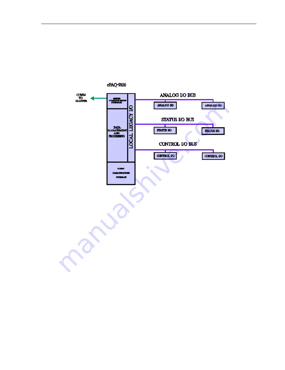
2.1   Substation Data Concentrator 


In this application the ePAQ is utilized as a traditional or legacy RTU. The field input is through 
QEI

’s 6AIP, 6SIP and 6COP hardware I/O panels. 


Summary of Contents for ePAQ-9100

Page 1: ...UG 1037 ePAQ 9100 December 2018 ...

Page 2: ...prove reliability function or design QEI does not assume liability arising out of the application or use of any product or circuit described herein neither does it convey any license under its patent rights nor the rights of others This manual and all data contained constitute proprietary information of QEI Inc and shall not be reproduced copied or disclosed to others or used as the basis for manu...

Page 3: ...Added Network Interface and Troubleshooting Sections September 2002 C Revised Operating Voltages October 2008 D Updated Ordering Information June 2009 E Fixed Diagrams removed ConfigWiz October 2010 F Formatting Update March 2012 G Formatting Update February 2016 H Formatting Update June 2017 I Updated QEI Address December 2018 ...

Page 4: ...rface 14 3 3 Local I O Interface 15 3 3 1 Analog Panel Interface API 15 3 3 2 Control Panel Interface CPI 15 3 3 3 Status Panel Interface SPI 16 3 4 Power Section 16 4 Software Description 16 5 Specifications 18 5 1 General Specifications 18 5 1 1 Port 1 2 RS 232 optional 18 5 1 2 Port 1 2 TELCO optional 18 5 1 3 Port 3 RS 232 Maintenance Port 19 5 1 4 Port 4 RS 232 Communications Port 19 5 1 5 Po...

Page 5: ... 8 Maintenance Port 30 6 4 ePAQ Addressing 31 7 Configuration 32 8 Troubleshooting 32 8 1 Recommended Equipment 32 8 2 Documentation Requirements 32 8 2 1 Post Installation Checkout Documentation 32 8 3 Communication ePAQ to Field Device s 33 8 4 Communications Master Station to ePAQ 35 8 5 IRIG B Troubleshooting 37 8 6 Network Interface Troubleshooting 37 8 7 Data Validation 37 8 7 1 Analog Data ...

Page 6: ...l outputs digital and analog inputs and various standard or user programmable automation functions at remote substations The ePAQ 9100 is a self contained unit that includes the central processor various types of memory communications interfaces A D converter select before operate SBO control and status processing The primary gateway application of the 6CPP6 is substation communications processing...

Page 7: ...e and report momentary changes of state for individual status points Monitor analog inputs and report their value to the master station each time an analog input value changes more than the preset deadband Execute controls in a highly secure select before operate manner with programmable execute durations on a per point basis Analog setpoint controls 1 millisecond sequence of event SOE time taggin...

Page 8: ...9100 6 Applications Copyright 2017 QEI 2 1 Substation Data Concentrator In this application the ePAQ is utilized as a traditional or legacy RTU The field input is through QEI s 6AIP 6SIP and 6COP hardware I O panels ...

Page 9: ...t protocols like DNP3 Modbus RTU or Cooper 2179 Also included as an example interface to an existing legacy RTU utilizing a proprietary protocol See block diagram below Because IED s can provide a large amount of data data management can be very cumbersome QEI s configuration program ConfigWiz can alleviate most if not all of the data management problem Using techniques called filtering and mappin...

Page 10: ...ns via 10 100BaseT or 100 Base FX The ePAQ 9100 can be configured with an Ethernet interface that supports both 10 100 Base TX or 100 Base FX The Ethernet Interface supports both UCA 2 0 OSI and TCP IP and DNP3 over TCP IP Data from existing Legacy RTU as well as IED s with serial communications interface can be added to the LAN See block diagram below ...

Page 11: ...the legacy master in its required format This configuration allows you to upgrade your substations with the latest IED s without having to upgrade your legacy Master Station The data filtering and mapping feature of ConfigWiz can be used to select essential data for transmission over a band limited communications facility to the master station This will reduce data volume and thereby decrease syst...

Page 12: ...s as well as servicing Master Station data requests it can support a web page The web page can be used as a local or remote HMI to view real time substation data while all of the other functions are being processed This feature is very useful when problems occur to ascertain causes and start troubleshooting See block diagram below ...

Page 13: ...l mathematical and closed loop control operations The ePAQ 9100 takes care of local control requirements without using vital communications channel time to send information and receive instructions from the Master Station The block diagrams shown below are an example of Feeder Automation in which pole top devices are communicating with the ePAQ 9100 The first example is of a serially connected sub...

Page 14: ...100 may optionally contain circuitry for up to nine 9 serial communication ports up to 2 Bell 202T modem ports up to 1 IRIG B interface port and up to 2 Ethernet ports Base T and Base FX Because the ePAQ 9100 can be configured in different ways not all of the ports discussed here may be available in every ePAQ The following are descriptions of the ommunications ports usage in a typical SCADA syste...

Page 15: ...ort utilizes the Serial Communication Interface built into the 68331 It is called the Maintenance Port because its main function is to provide a clean simple interface to the test technician allowing him to control and query the status of the ePAQ 9100 or its data This port is also used for downloading software configuration tables etc This is an RS 232 interface port supporting only software hand...

Page 16: ... ePAQ These ports conform to the RS 485 specification and are suitable for direct wiring with external IEDs High speed opto couplers provide isolation while fast Schottky Zener diodes and surge suppressing capacitors clamp any input voltage transient and noise to chassis ground Terminal blocks are used to provide connections to external devices NOTE Ports 6 7 and 8 can be either RS 232 or RS 485 c...

Page 17: ...A D converter that converts collected analog values to digital values These values are then stored in RAM A DC DC converter in the ePAQ provides power and isolation for the 6AIP1 s A 16 pin IDC header ANALOG is used to connect the ePAQ 9100 to the 6AIP1 s via ribbon cable 3 3 2 Control Panel Interface CPI The Control Panel Interface CPI provides the means for the system to momentarily energize ext...

Page 18: ...ng Via a 26pin IDC header STATUS 6SIP1 s can be connected to the ePAQ 9100 via ribbon cable 3 4 Power Section The ePAQ 9100 can operate at one of three operating voltages 120VAC 125VDC or 20 60 VDC From this single input voltage the ePAQ 9100 makes of the internal voltages required to drive all of the logic and communications circuits Also the ePAQ 9100 generates the voltage required to drive Loca...

Page 19: ...des This data handling model is very effective in providing proper interactions between very different protocols ERTOS provides a uniform configuration interface for all components which is extended with special purpose options for protocol specific requirements The system wide point routing allows any set of data points or controls to be available to each server and allows them to be mapped to an...

Page 20: ...remote access and maintenance FTP TFTP and HTML access are provided for reading and writing configuration information as well as for providing data in XML or JavaScript compatible formats as a Web Server Telnet is supported for access to the diagnostic utilities PPP or SLIP protocols are available for dial up applications and the file system supports NFS access for applications that can take advan...

Page 21: ...9 RS 232 Communication Ports optional Protocols Asynchronous byte oriented Data Rate Up to 38 4 Kbps Push To Talk Open collector 120mA 12Vdc sinking Interconnections DB9 Female 5 1 7 Port 6 7 8 RS 485 Communications Ports optional Protocols Synchronous asynchronous byte oriented Interface 2 Wire RS 485 optically isolated Data Rate Up to 38 4 Kbps Connector 4 pin terminal block 5 1 8 IRIG B Interfa...

Page 22: ...tting voltage for the status points is NOT generated by the ePAQ 9100 A separate power supply for this operation must be supplied 5 1 12 Control Output Port Addressability 128 points in up to 16 QEI 6COP1 panels Number of Columns 16 Number of Rows 8 pairs 8 Trip 8 Close Drive Voltage 30 VDC nominal Control Pulse Duration 250 msec default Relay Coil Resistance 225 to 528 ohms Security One relay ope...

Page 23: ...to 95 70 C non condensing 5 1 16 5 1 16 Weight Approx 10 lbs 6 Installation 6 1 ePAQ Mounting See Figure 6 1 for mounting dimensions and spacing Mounting screws 10 32 x 0 5 not included Enough space behind the rear of the ePAQ must be provided for all communication and power connections a minimum for 4 is recommended Figure 6 1 Mounting Dimensions ...

Page 24: ...UG 1037 ePAQ 9100 22 Installation Copyright 2017 QEI Figure 6 2 Front Panel ...

Page 25: ...that the ground connection is made and is in working condition This is the chassis ground for the unit WARNING Before applying power to the ePAQ make certain that the power and ground connections are made to the correct terminals and that they are secure Failure to do so may result in unit damage or personal injury NOTE Be sure that the power input wires are routed away from any communications cab...

Page 26: ...S 485 port It is suitable for use to connect to intelligent field devices that support 2 wire RS 485 communications Figure 6 6 shows the pin connections for the RS 485 Port 5 Figure 6 6 Port 5 Wiring 6 3 3 Port 1 and Port 2 202T or RS 232 optional Port 1 and 2 can be configured as either a 202T Modem or RS 232 connection Check the part number of the ePAQ to determine if it is equipped with either ...

Page 27: ...t the same time Table 6 1 below describes the relationship between the ePAQ ordering information type of port 1 or 2 and the figure to refer to for wiring information Table 6 1 Port 1 and 2 Wiring Connections ePAQ Ordering Port 1 Type Port 1 Figure Port 2 Type Port 2 Figure EPAQ 9100 X 0 X X None None None None EPAQ 9100 X 1 X X 202T 6 7 RS 232 6 8 EPAQ 9100 X 2 X X RS 232 6 8 RS 232 6 8 EPAQ 9100...

Page 28: ...er settings and Figure 6 9 shows jumper locations for an ePAQ 9100 equipped with 1 202T modem port Port 1 and 1 RS 232 port Port 2 The jumpers must be set for proper operation of the 202T modem port Table 6 2 Single 202T Port Jumper Settings Jumper Function JP7 Modem Receiver Sensitivity IN 30 dBm OUT 45 JP8 dBmTransmitter Gain This jumper group has five individual positions from 12 dBm to 0 dBm i...

Page 29: ... dBm OUT 4__5 Bm JP2 JP7 Transmitter Gain 1 2 0 dBm 3 4 3 dBm 5 6 6 dBm 7 8 9 dBm _______ 9 10 12 dBm__________________________________ JP1 JP6 2 Wire 4 Wire Operation This jumper group has three individual positions as marked 4Wire 2 jumpers one in each END position _____________ _ 2 Wire 1 jumper in the MIDDLE position _____________ JP10 JP12 Install for pre emphasis____________________________ ...

Page 30: ...ional These ports are optional in the ePAQ and are included if the ePAQ part number is ePAQ 9100 X X 1 X Port 9 is only a RS 232 port NOTE The port can be either a RS 232 or RS 485 but not both simultaneously Figure 6 11shows the pin connections for both RS 232 and RS 485 for Ports 6 7 8 and 9 Figure 6 11 Port 6 9 RS 232 RS 485 Wiring ...

Page 31: ...5 xxx specify length in feet Status Input Cable 30 057917 xxx specify length in feet Control Output Cable 30 057916 xxx specify length in feet NOTE The ePAQ does not supply status contact wetting voltage for the 6SIP1 Status Input Panels This voltage must be externally supplied directly to the 6SIP1 s via the provided connections For more specific information on the QEI Local I O panels please see...

Page 32: ...ility to be time synchronized by external IRIG B time receiver via either the analog BNC connection or the digital RS 422 connection Figure 6 14 IRIG B Interface 6 3 8 Maintenance Port Refer to Figure 6 15 and Section 1 General Specifications for connection and detailed technical information on the ePAQ Maintenance Port Use a null modem RS 232 cable to connect a PC or laptop PC running a terminal ...

Page 33: ...2 Refer to Figure 6 16 for S2 location This dipswitch sets the least significant byte of the station address according to the table below Prior to setting this address be sure to consult the protocol s using this station address to ensure that is within the appropriate range Switch Value 1 1 2 2 3 4 4 8 5 16 6 32 7 64 8 128 Figure 6 16 ePAQ Addressing DIP Switch Locations Non Shaded area in drawin...

Page 34: ...2000 Test Set for monitoring and deciphering messages between the Master Station and the ePAQ and or the ePAQ and any connected IED s is very useful 8 2 Documentation Requirements 8 2 1 Post Installation Checkout Documentation For basic post installation checkout procedures the following documentation is required This Instruction Manual The specific documentation package outlining the system which...

Page 35: ... Maintenance port see the command set list later in this section In order to best troubleshoot a communication link a hardware protocol analyzer or in line protocol test set should be used The ePAQ does not try to send a message to the Field Device Problem Solution Is power supplied to both the ePAQ and the Field Device Check power to each unit On the ePAQ verify that the Heartbeat LED on the Fron...

Page 36: ...n ePAQ file and change if necessary Refer to Configuring Communication Ports in Section 3 of this manual Does the Field Device address in the configuration match the actual Field Device s address Check the address as specified in the Field Device configuration in the file Refer to the appropriate ConfigWiz protocol addendum Also check the address as configured in the Field Device itself Is the Fie...

Page 37: ...ink between the Master Station and the RTU The Master Station is sending a message to the ePAQ but the ePAQ does notreceive it The RX LED may light up whenever data good or garbage is received at the port If the LED does not light up it is usually a cabling problem Problem Solution Is the Configuration file downloaded to ePAQ Re write the file to the ePAQ Does the configuration file contain the co...

Page 38: ...e information Is there data mapped to the Master Station in the ePAQ configuration file Check that there is data mapped to the Master Station under test Refer to Configuring Servers in Section 3 of this manual Does the protocol implementation support the message type being sent by the Master Station Consult with QEI Technical Assistance for more information The ePAQ responds to Master Station s me...

Page 39: ...the ePAQ or from the ePAQ to the Master Station Use the diagnostic commands to query the ePAQ for analog status and accumulator data or to actuate a control relay Refer to Diagnostic Command Set in this section The diagnostic commands display data based on the point addresses starting from address 0 of the data as they are mapped into the first Master Station server added to the ePAQ configuration...

Page 40: ...ice Allow a sufficient amount of time for the ePAQ to poll and receive an updated value for the point At this point in the Analog data validation process all options concerning software parameter adjustments have been attempted Check that all wiring terminations and cabling are correct If those are correct contact QEI for technical assistance 8 7 2 Status Data Status Data displayed by the Maintena...

Page 41: ...Status data validation process all options concerning software parameter adjustments have been attempted Check that all wiring terminations and cabling are correct If those are correct contact QEI for technical assistance 8 7 3 Accumulator Data Problem Solution Point value is FAIL instead of a value Check that communications are still functioning to the Field Device Check that the Field Device has...

Page 42: ...to the appropriate ConfigWiz protocol addendum for more information If the control point is a Latching type check the current state of the control point Then send the opposite control point command At this point in the Control data validation process all options concerning software parameter adjustments have been attempted Check that all wiring terminations and cabling is correct If those are corr...

Page 43: ...QEI P N 10 057126 001 Use to connect the ePAQ Maintenance Port to a PC s RS 232 port Maintenance Port Laptop PC QEI P N 40 057589 001 A laptop PC with Maintenance Port cable The laptop can be used to configure the ePAQ with the ConfigWiz software and troubleshoot the ePAQ with Hyperterminal or equivalent terminal emulator 9 1 2 Software ConfigWiz CD QEI P N 80 000063 001 This is a CDROM which incl...

Page 44: ...er s Guide This manual 6AIP1 User s Guide QEI P N UG 1003 This manual describes the QEI Local I O Analog Input Panel 6SIP1 User s Guide QEI P N UG 1005 This manual describes the QEI Local I O Status Input Panel 6COP1 User s Guide QEI P N UG 1004 This manual describes the QEI Local I O Control Output Panel 6TIM1 User s Guide QEI P N UG 1036 This manual describes the QEI IRIG B Interface Board 6NIA1...

Page 45: ...idual point of the data set Default Pre configured settings that are retained unless they are modified by the user Display Representation of an item in the GUI Double click Selecting a command or icon twice in rapid succession using the left half of the mouse Driver A program written to perform a specific function Field An area in a window or pop up window where information is displayed entered or...

Page 46: ...f the window when for example there are two or more sections in a window Parameter A variable that requires input from the user according to the system needs PC Personal computer A personal computer may be referred to as a PC or computer and may be either a desktop or laptop Pop up window A window that displays as a result of selecting a command Pop up windows usually display when more information...

Page 47: ...ve representation of the system that depicts all the equipment location of the equipment and specific system parameters System Configuration The process of coordinating all the requirements for the master station RTUs and communication facilities Tab A labeled area in a window that the user selects to display the information contained in that window for that particular tab Template A custom struct...

Reviews: