- 84 -
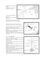
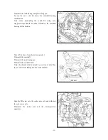
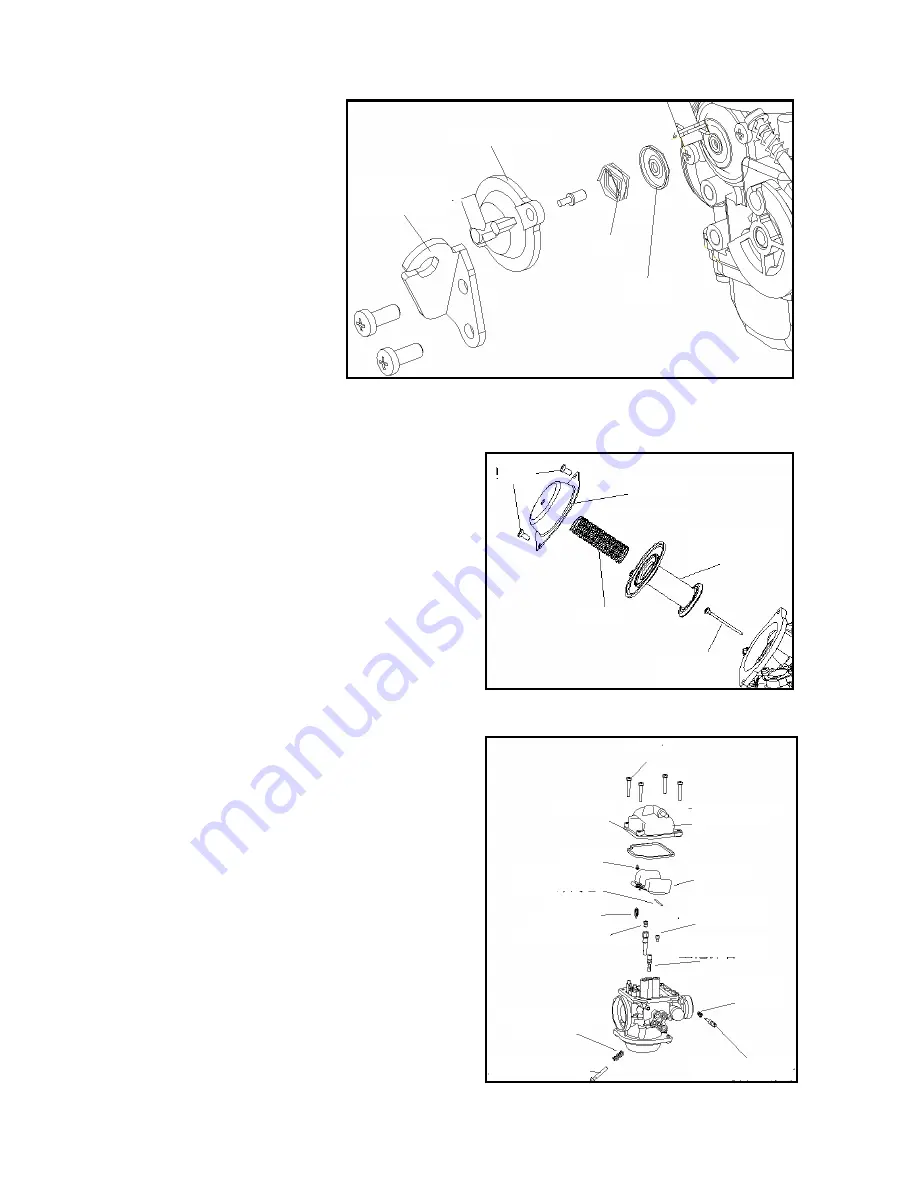
Dismantle the throttle pulling-line
fixed plate.
Dismantle the air throttle cover,
spring and the air throttle.
Loosen the bolt and dismantle the
upper cover.
Take out the spring and the plunger
components.
Examine the attrition condition of the plunger.
If the plunger is worn down, it should be replaced.
Examine the attrition condition of the needle valve.
If the needle valve is worn down, it should be replaced.
Loosen the fastening screw of the drag shell body, and
dismantle the components and the joint ring.
Dismantle the float components, floater-pin and needle
valve core.
Dismantle the idle metering hole, the main metering hole,
the main nozzle and the main foam tube.
Dismantle idle adjusting screw, and the idle screw spring.
Dismantle the mixture-ratio screw and the mixture-ratio
screw spring.
10.3.3
Examination
Examine if the needle valve core, needle valve and the float
components are damaged or worn down .
If the needle valve core is damaged or worn down, it
should be replaced.
If the needle valve seat is worn down, then the carburetor
body should be replaced.
If the float tongue piece is worn down, it should be
replaced.
Examine the oil needle of the carburetor to see if it is
damaged or worn down. If so, the oil needle as well as the
main nozzle should be replaced.
Examine the idle metering hole, the main metering hole
and the main nozzle to see if they are damaged, worn down
or stained. If so, they should be replaced.
Examine the plunger to see if it is worn down. If so, it
should be replaced.
Examine the carburettor body and the oil-fired pipe. If they
are stained, please clean them as per the instruction book.
Air throttle cover
Fixed plate of
throttle pulling-line
Spring
Air throttle
Bolt
Upper cover
Spring
Plunger
components
Oil needle
Bolt
Sealing ring
Floater pin
Idle metering hole
Floater
Needle valve core
Main foam tube
Idle adjusting screw
spring
Idle adjusting screw
Main metering hole
Main nozzle
Mixture-ratio
screw spring
Lower shell body
Mixture-ratio screw
Summary of Contents for QJ150T-10
Page 15: ... 14 QJ150 10 ...
Page 73: ... 72 Rear wheel rear suspension ...
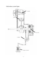
Page 78: ... 77 Lubrication system figure engine oil strainer oil pump bent axle camshaft piston ...
Page 87: ... 86 ...
Page 97: ... 96 ...
Page 104: ... 103 ...
Page 113: ... 112 Output axle Middle axle Input axle ...
Page 116: ... 115 The assembly of bearings and oil seal should use special tools to prevent damage ...
Page 125: ... 124 Muffler ...
Page 131: ... 130 ...

