QY-IMX6S Hardware Manual
Any question, please send E-mail
Page 10 of 27
Sales E-mail
:trade@qiyangtech.com
sales@qiyangtech.com
Website
:http://www.qiytech.com
©2012 Qiyangtech
Copyright
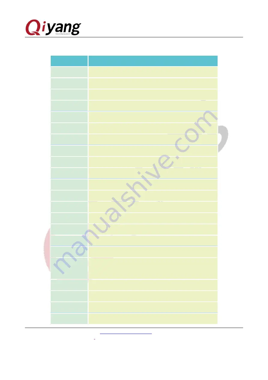
3.1 Basic Interface Function Description
Label
Function
J1
+12V Power supply input
J2
UART and CAN
J4
BOOT mode selection
J5
SPI and 2*4GPIO
J6
Debug Port
J7
BOOT mode selection
J8
JTAG
J10
USB OTG
J11
2-ch USB
J12
USB, can connect to external module
J13
Gigabit Ethernet
J14
SD Card
J15
HDMI
J16
LVDS1
J17
LVDS2
J18
LCD Power supply
J19
Capacitive Touch Panel
J21
LCD TTL Interface, integrate 4-wire resistive touch panel
interface
J22
CAMERA
J24
VGA
J25
MIC Audio input
J26
Audio output


