background image

2

70

L

41

40

40

54

26

9

43

41

41

41

41

76

70

6-Ø4 HOLES

Ø13 

CABLE ENTRY

21

8

27.

5

Ø70

LAYER

L

1

121

2

162

3

203

4

244

5

285

Dimensions

QWT

Specification

• Protection rating : IP54

• Ambient operating temperature : -30°C to +50°C

Current Specifications

Voltage 

Condition

AC/DC12V AC/DC24V

AC110-220V

Light

(per Layer)

0.065A

0.050A

Max 0.025A

Buzzer

0.034A

0.078A

Max 0.016A

AC type model has a free-voltage range of  AC100V-240V.

Model

Number

Layer

Voltage

Current

Certificate Weight

Color

QWTL

Steady type

QWTL - BZ

Steady type with 

built-in buzzer

QWTLF

Steady/Flashing 

type

QWTLF - BZ

Steady/ Flashing 

type with built-in 

buzzer

1

AC/DC12V

0.065A

DC only

DC24V 

only

0.34kg

R-Red

AC/DC24V

0.050A

0.34kg

AC110V-220V Max. 0.025A

0.36kg

2

AC/DC12V

0.130A

0.41kg

R-Red

G-Green

AC/DC24V

0.100A

0.41kg

AC110V-220V Max. 0.050A

0.43kg

3

AC/DC12V

0.195A

0.48kg

R-Red

A-Amber

G-Green

AC/DC24V

0.150A

0.48kg

AC110V-220V Max. 0.075A

0.50kg

4

AC/DC12V

0.260A

0.55kg

R-Red

A-Amber

G-Green

B-Blue

AC/DC24V

0.200A

0.55kg

AC110V-220V Max. 0.100A

0.57kg

5

AC/DC12V

0.325A

0.62kg

R-Red

A-Amber

G-Green

B-Blue

W-White

AC/DC24V

0.250A

0.62kg

AC110V-220V Max. 0.125A

0.64kg

Installation Environment and Protection Rating

• 

This product is designed for indoor use with an enclosure ingress protection rating of IP54.

• If the product is installed in locations with excessive dust or water other than the designated IP protection rating indicated (IP54), 

   it may cause malfunction or damage to the product.

• For further information, please visit our website at http://www.qlight.com.

(Unit : mm)

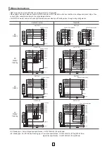
Summary of Contents for QWT Series

Page 1: ...nction or damage to the product fire and electric shock Precautions for Correct Use Failure to follow the proper instructions may cause damage to property the product and or malfunction of the product that would void the warranty 1 During wiring or maintenance please completely turn off the power of the product Failure to follow this may lead to an electric shock 2 Do not install the product in lo...

Page 2: ...24V 0 050A 0 34kg AC110V 220V Max 0 025A 0 36kg 2 AC DC12V 0 130A 0 41kg R Red G Green AC DC24V 0 100A 0 41kg AC110V 220V Max 0 050A 0 43kg 3 AC DC12V 0 195A 0 48kg R Red A Amber G Green AC DC24V 0 150A 0 48kg AC110V 220V Max 0 075A 0 50kg 4 AC DC12V 0 260A 0 55kg R Red A Amber G Green B Blue AC DC24V 0 200A 0 55kg AC110V 220V Max 0 100A 0 57kg 5 AC DC12V 0 325A 0 62kg R Red A Amber G Green B Blue...

Page 3: ...Power Power Common Common Common Common Common Common Common Common Common Common 1 2 3 4 5 1 2 3 4 5 1 2 3 4 5 Flash External Contact External Contact External Contact External Contact Red R Amber A Green G Blue B White W Red R Amber A Green G Blue B White W Brown BN Red R Amber A Green G Blue B White W Brown BN Red R Amber A Green G Blue B White W Brown BN Red R Amber A Green G Blue B White W Br...

Page 4: ...two M4 screws from the speaker unit Mount the mounting bracket to the mounting surface Hook the rear of the head cover to the upper bracket then push the body against the mounting bracket After tightly attaching the product body to the mounting bracket tighten the two M4 screws removed in step at the bottom of the speaker unit M4 25 BOLT M4 25 BOLT M4 25 BOLT M4 25 BOLT 41 41 41 41 43 21 41 41 41 ...

Reviews: