3
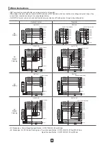
Wiring Instructions
• QWT series can be wired with either an external contact or a transistor.
• When using a transistor, please choose the NPN transistor or PNP transistor which best matches the voltage and product type, then
connect them correctly according to the wiring diagram below.
• For QWTDLF model, user can choose light function between steady and flashing mode through wiring configuration.
• DC Steady type : Power/ Signal line specification : UL1007 AWG22 (0.3sq) 400mm
• AC Steady type, AC/ DC Steady/ Flashing type : Power line specification : UL1015 AWG18 (0.75sq)X2C 400mm
Signal line specification : UL1007 AWG22 (0.3sq) 400mm
External Contact
Transistor
DC
Steady
QWTL-DC
QWTL-DC
DC
Steady/
Flashing
QWTLF-DC
QWTLF-DC
AC
Steady
QWTL-AC
QWTL-AC
AC
Steady/
Flashing
QWTLF-AC
QWTLF-AC
1
2
3
4
5
1
2
3
4
5
1
2
3
4
5
1
2
3
4
5
External Transistor-PNP
External Transistor-PNP
External Transistor-PNP
External Transistor-PNP
1
2
3
4
5
Buzzer
Buzzer
Buzzer
Buzzer
Buzzer
1
2
3
4
5
Fuse
Fuse
Fuse
Fuse
Fuse
Fuse
Fuse
Fuse
Fuse
Steady
Steady
Steady
Steady
Steady
Steady
Steady
Steady
Power
Power
Power
Power
Power
Common
Common
Common
Common
Common
Common
Common
Common
Common
Common
1
2
3
4
5
1
2
3
4
5
1
2
3
4
5
Flash
External Contact
External Contact
External Contact
External Contact
Red(R)
Amber(A)
Green(G)
Blue(B)
White(W)
Red(R)
Amber(A)
Green(G)
Blue(B)
White(W)
Brown(BN)
Red(R)
Amber(A)
Green(G)
Blue(B)
White(W)
Brown(BN)
Red(R)
Amber(A)
Green(G)
Blue(B)
White(W)
Brown(BN)
Red(R)
Amber(A)
Green(G)
Blue(B)
White(W)
Brown(BN)
Red(R)
Amber(A)
Green(G)
Blue(B)
White(W)
Brown(BN)
Brown(BN)
Black(BK)
Red(R)
Amber(A)
Green(G)
Blue(B)
White(W)
Red(R)
Amber(A)
Green(G)
Blue(B)
White(W)
Brown(BN)
Black(BK)
Brown(BN)
Black(BK)
Black(BK)
White(W)
Black(BK)
Black(BK)
White(W)
Black(BK)
Black(BK)
Gray(GR)
White(W)
Black(BK)
Black(BK)
White(W)
Black(BK)
Black(BK)
White(W)
Black(BK)
External Transistor-NPN
Layer1
Layer1
Layer1
Layer1
Layer1
Layer1
Layer2
Layer2
Layer2
Layer2
Layer2
Layer2
Layer3
Layer3
Layer3
Layer3
Layer3
Layer3
Layer4
Layer4
Layer4
Layer4
Layer4
Layer4
Layer5
Layer5
Layer5
Layer5
Layer5
Layer5
Buzzer
Buzzer
Buzzer
Buzzer
Power
Power
Power
Power
Layer1
Layer1
Layer1
Layer1
Layer1
Layer2
Layer2
Layer2
Layer2
Layer2
Layer3
Layer3
Layer3
Layer3
Layer3
Layer4
Layer4
Layer4
Layer4
Layer4
Layer5
Layer5
Layer5
Layer5
Layer5
Common
Steady
Flash
Red(R)
Amber(A)
Green(G)
Blue(B)
White(W)
Brown(BN)
Gray(GR)
Black(BK)
White(W)
Black(BK)


