4
Step 2. Mount the Switch
1.
Install applicable rack mounting hardware and switch in a standard 19" rack as described in the
QLogic
12000 Hardware Installation Guide
.
Step 3. Apply Power to the Switch
NOTE:
Refer to
QLogic 12000 Hardware Installation Guide
for applicable safety warnings.
1.
Attach the AC power cord(s) to the switch and wall outlets or power strips.
2.
When the switch is plugged into an AC power outlet:
a.
The system powers up.
b.
The fans start.
c.
The switch, power supply, and fan LEDs light up.
NOTE:
For the 12800 switches, make certain the DC On switch is illuminated. If it is not, press
the button to supply power.
Step 4. Connect Cables
1.
Connect a Category 5 or 6 (Cat 5/6) Ethernet cable to the RJ-45 connector(s) on the switch. Connect
the other end of the Cat 5/6 to the OOB LAN workstation or Ethernet switch.
2.
12800 series: Connect a DB-9 to RJ-11 adapter to each RJ-11 cable. Connect the cable(s) to the
switch serial ports.
3.
12300/12400: Connect an RJ-11 cable to each serial port on the switch.
4.
Connect the switch to IB-enabled hosts using QSFP IB copper or fiber-optic cables.
Step 5. Change the Default System IP Address and Gateway IP Address
1.
Change the default system IP address (192.168.100.9) and gateway IP address (255.255.255.0) as
detailed in the
QLogic 12000 Hardware Installation Guide
. Obtain the new IP address and subnet mask
from a network administrator.
Step 6. Add equipment to the network
RJ-11 Serial
cable
N/A
1
1
2
2
2
2
Power Cords
2
2
2
4
4
6
12
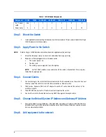
Table 1. 12000-Series Components
Component
12200
12300
12400-6/12
12800-040
12800-120
12800-180
12800-360
Summary of Contents for InfiniBand 12200-BS01
Page 10: ...10...


