7–Removal and Replacement
iSR6200 Chassis Blades
7-8
ISR651101-00 G
2.
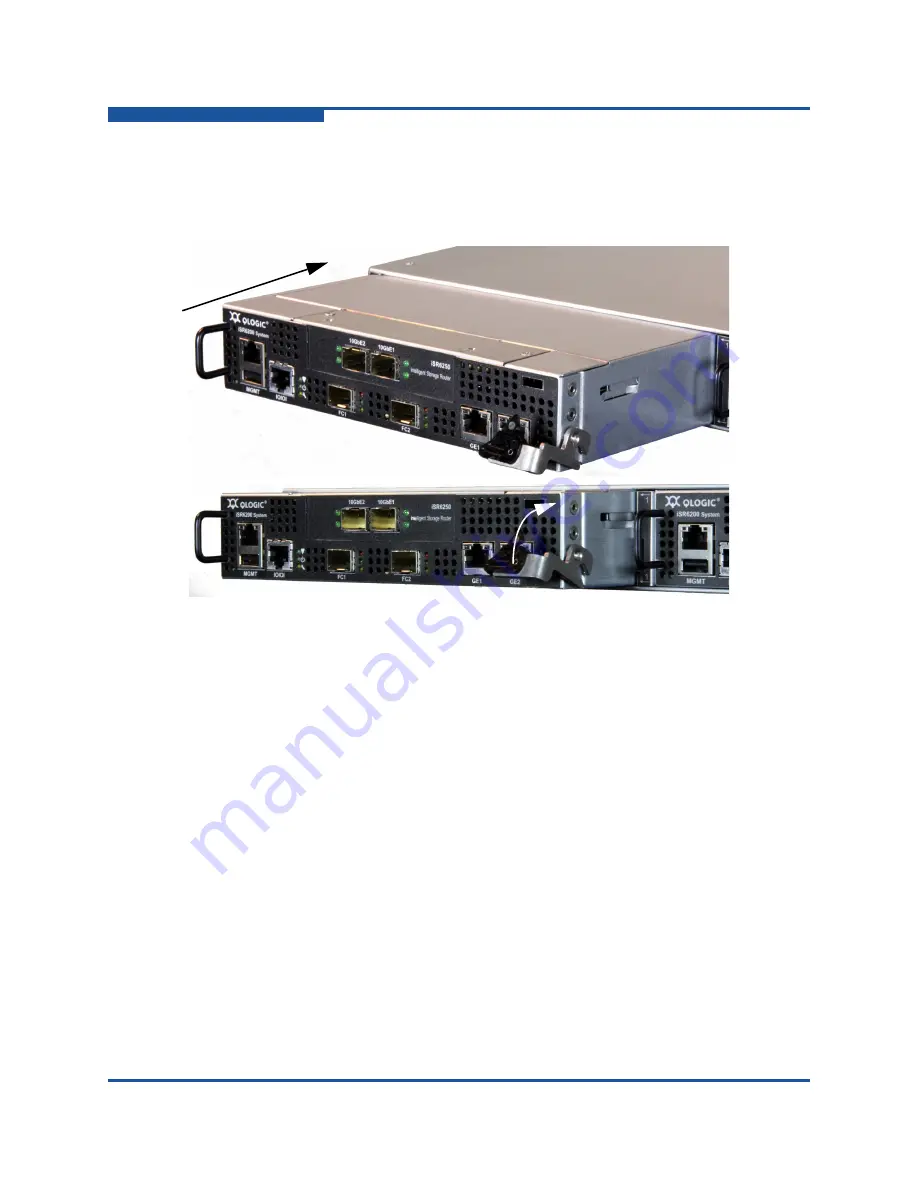
Insert the new blade into the chassis slot.
shows how to push the
blade straight into the chassis (1), seat the blade onto the chassis mid-plane
by pushing the right side lever up, and then latching it into place (2). The
blade powers on and boots up.
Figure 7-8. Inserting the New Blade into the Chassis Slot
3.
Wait until the blade finishes booting up.
The system runs the POST. The heartbeat and system fault LEDs show the
operational status of the router. When the POST completes with no errors,
these LEDs blink at a steady rate of once per second.
4.
Connect to the blade’s Ethernet management interface to your computer.
5.
Open a command line, change to the directory that contains your FRU file,
and then enter
ftp 10.0.0.1
. For both the user name and password, use
ftp
. Remember to enter the
bin
command before you enter the
put
command. For example:
(1)
(2)
Summary of Contents for iSR6200
Page 1: ...ISR651101 00 G iSR6200 Intelligent Storage Router Installation Guide ...
Page 20: ...Preface Technical Support xx ISR651101 00 G ...
Page 34: ...1 Introduction iSR6200 Router Blades 1 14 ISR651101 00 G ...
Page 60: ...3 Installation Installing New Firmware 3 18 ISR651101 00 G ...
Page 90: ...4 Configuration Controlling per Host LUN Access on the iSR6200 4 30 ISR651101 00 G ...
Page 110: ...5 Fibre Channel over IP Configuring FCIP 5 20 ISR651101 00 G ...
Page 128: ...7 Removal and Replacement Power and Cooling Modules 7 14 ISR651101 00 G ...
Page 134: ...A Technical Specifications Environmental and Safety A 6 ISR651101 00 G ...
Page 160: ...B Simple Network Management Protocol Notifications B 26 ISR651101 00 G ...
Page 217: ......


