background image

1–Operations and Administration

Configuration and Monitoring Features

D000101-000  E

1-37

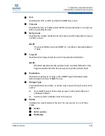
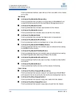
Figure 1-53  Upload Window

2.

Type the path to the desired server location, or click 

Browse

 to locate the 

correct path.

3.

Click

 Submit

.

To download a configuration file from the switch to a server:

1.

For a selected module, click the 

Download

 button. The 

File Download 

window is displayed.

2.

Click 

Save

.

3.

In the 

Save As

 window, locate the correct path to the desired server 

location, and click 

Save

.

Trap Control

The 

Trap Control

 window allows the user to set default trap scenarios related to 

configuration files.

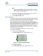
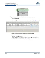
1.

From the Chassis menu, select 

Config File Admin

.

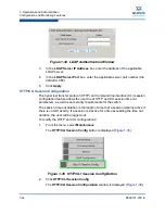
The 

Trap Control

 button is displayed (

Figure 1-54

).

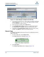
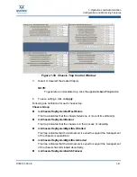
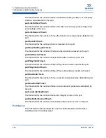
Figure 1-54  Trap Control

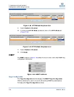
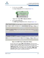
2.

Click 

Trap Control

Summary of Contents for QLogic 12000 Series

Page 1: ...D000101 000 E QLogic 12000 Series InfiniBand Switches and Directors User Guide Version 6 0...

Page 2: ...specifications at any time without notice Applications described in this document for any of these products are for illustrative purposes only QLogic Corporation makes no representation nor warranty t...

Page 3: ...e and Management Module Views 1 4 Leaf Module View 1 4 Spine Module View 1 5 Management Module View 1 6 Component Details Area 1 7 Details Header 1 7 Module Information Area 1 8 Chassis View Component...

Page 4: ...Statistics 1 47 Set Field Thresholds 1 49 Port Beacon 1 51 Time Service 1 54 OOB LAN IP Submenu 1 57 Configuring the Switch OOB IP Address 1 57 Configuring the Switch Default Gateway IP Address 1 58 F...

Page 5: ...25 Device Tab Software Module Configurator 1 16 1 26 Log System Configurator Preset Tab 1 18 1 27 Log System Configurator Syslog Host Tab 1 19 1 28 Reset Levels Button 1 20 1 29 Reset Log Levels Wind...

Page 6: ...Thresholds 1 49 1 67 Set Field Thresholds Window 1 49 1 68 Port Beacon 1 52 1 69 Port Beacon Window 1 53 1 70 Port Beacon Highlight 1 54 1 71 Switch Time Service 1 54 1 72 System Time Information Win...

Page 7: ...ser Guide 1 94 Subnet Manager Control Button 1 65 1 95 Subnet Manager Control Window 1 66 1 96 License Key Submenu 1 67 1 97 Key Management Window 1 67 1 98 License Key Management Information Window 1...

Page 8: ...viii D000101 000 E QLogic 12000 Series InfiniBand Switches and Directors User Guide...

Page 9: ...sk information for the switches Documentation Conventions This guide uses the following documentation conventions NOTE provides additional information CAUTION indicates the presence of a hazard that h...

Page 10: ...r example For a complete listing of license agreements refer to the QLogic Software End User License Agreement What are shortcut keys To enter the date type mm dd yyyy where mm is the month dd is the...

Page 11: ...ng QLogic products Upon demonstrating knowledge using live equipment QLogic awards a certificate identifying the student as a Certified Professional The training professionals at QLogic may be reached...

Page 12: ...Preface Technical Support xii D000101 000 E...

Page 13: ...InfiniBand networks Chassis Viewer runs on the firmware of the 12300 and each management module of the 12800 series The browser must be on a workstation which has IP connectivity to the LAN port RJ 45...

Page 14: ...director class management module Logging and monitoring functionality Home Page Chassis Viewer s home page Figures 1 2 and 1 3 provides a high level overview of the switch This area is the starting p...

Page 15: ...fic description Figure 1 4 Help Button Displaying the Chassis View There are three ways to display the chassis view for the 12800 switches First Way 1 Mouse over the outer region of the leaf module vi...

Page 16: ...odule view The edges of the chassis are highlighted green as shown in Figure 1 6 below Figure 1 6 Management Module View Mouseover 2 Click the outer region of the management module view The chassis vi...

Page 17: ...e to display The edges of the leaf module are highlighted green as shown in Figure 1 8 below Figure 1 8 Leaf Module Mouseover 2 Click the leaf module The leaf module view is displayed Figure 1 9 Figur...

Page 18: ...played Figure 1 11 Figure 1 11 Spine Module View Management Module View To display the management module view 1 Mouse over the management module to display The edges of the module are highlighted gree...

Page 19: ...Figure 1 14 for the chassis spine leaf and management module has three areas Details Header Information area Menu Figure 1 14 Component Details Area Details Header The Details Header Figure 1 15 allow...

Page 20: ...ion areas Chassis View Component Information Area The Chassis View Component Information Area Figure 1 17 allows the user to monitor important information for each specific hardware component as well...

Page 21: ...ow to be modified 3 In the text boxes enter information that is applicable to the existing network environment 4 To save click the Apply button at the bottom of the window Rebooting the 12300 Switch 1...

Page 22: ...he tabs along the top of the information area present information about the following components LED and sensor information Overall system information Switch Field Replaceable Unit FRU Information Pow...

Page 23: ...stem Tab The System tab displays overall system information for the applicable switch chassis This information includes the following items Out of Band LAN IP The IP address of the switch The IP addre...

Page 24: ...is to use the system s fully qualified domain name System Location The location of the system assigned by an administra tor Apply Button Saves any changes made by the user in the System tab to memory...

Page 25: ...or each row that displays additional detail about the component Additional details include Description Status Part Number Manu facturing Name Product Name and Manufacturing ID Apply Button Saves any c...

Page 26: ...administrative tasks related to the configuration Refer to Configuration File Administration on page 1 33 Set default trap scenarios related to the switch Refer to Chassis Traps on page 1 40 Obtain IB...

Page 27: ...be logged into Ram Device or the Syslog Device Any unselected levels will not be logged to any Device The second layer is the Device Levels This allows the user to select the levels of log messages t...

Page 28: ...ettings for the following software modules RAM The circular log buffer contained in memory To access the contents of this buffer use the Chassis Viewer View Log button Syslog Messages that are sent to...

Page 29: ...he user retrieve the dump that was produced Support engineers may require the information contained in the dump file to diagnose the cause of the problem FATAL Indicates that a non recoverable system...

Page 30: ...s not need to take action NOTICE Notice is used for failures that could be a result of frequent user actions such as a server reboot Debug message levels 1 through 5 Debug messages are for supplier an...

Page 31: ...right of the setting s 2 Click the Apply button to save any changes Syslog Host Tab The Syslog Host tab Figure 1 27 allows the user to configure logging messages to be sent to a syslog host through a...

Page 32: ...e etc sysconfig syslog file and ensure that the r is included in the SYSLOGD_OPTIONS This allows logging from a remote system For example SYSLOGD_OPTIONS r m 0 2 Type etc init d syslog restart and pre...

Page 33: ...3 To reset the logging levels click OK Maintenance The Maintenance menu Figure 1 30 allows the user to select an alternate firmware file for the switch reboot the switch set and configure authenticat...

Page 34: ...e menu select Maintenance The Firmware Update button is displayed Figure 1 31 Figure 1 31 Firmware Update Button 2 Click Firmware Update The Firmware Update window is displayed Figure 1 32 Figure 1 32...

Page 35: ...and rather than authenticating internally encrypts and packages the information in an LDAP packet and sends it to a pre configured LDAP server over TCP IP i e the out of band LAN The LDAP server recei...

Page 36: ...configuration feature allows the user to set HTTP and CLI session time out parameters as well as set security requirements for the switch The session time out duration is the length of time that a ses...

Page 37: ...nge the User Authentication parameter click on the User Authentication list Figure 1 37 Figure 1 37 User Authentication Dropdown List 7 Select the preferred user authentication method These are Login...

Page 38: ...1 39 Figure 1 39 HTTPs Mode Dropdown List 11 Select Enabled or Disabled 12 Click Apply SNMP The SNMP submenu Figure 1 40 allows the user to view and modify SNMP trap configuration information Figure...

Page 39: ...Target Configuration Window The top section of the window SNMP Target Addresses allows the user to determine what type of SNMP traps are sent and where they are sent The rows provide an area for spec...

Page 40: ...target except using SNMP v1 traps snmpTargetAddr add n traphost1 a 192 168 0 123 v v1 params Target Configuration Window Field Descriptions The following are descriptions for each field in the Target...

Page 41: ...a mapping to an entry in the SNMP Target Parameters table determining the version of SNMP to use Storage Type This field determines whether or not the entry is saved for each reboot of the switch Nonv...

Page 42: ...or this field are 1 for SNMP v1 2 for SNMP v2 or 3 for SNMP v3 Security Name Security name identifies the entity for whom SNMP messages will be generated Security Level One of three options NoAuthNoPr...

Page 43: ...ve Not in service Not Ready Filter Status The SNMP Filter Status window allows the user to view parameters for rfc2273 SNMP NOTIFICATION MIB To view SNMP filter status 1 From the menu select SNMP The...

Page 44: ...nity Strings window allows the user to set two SNMP community names Read Only Community Name Read Write Community Name To set the Community Strings 1 From the menu select SNMP The Set Community String...

Page 45: ...s exported by the SNMP server 3 In each text box enter a meaningful name such as public and private shown above and click on Apply Configuration File Administration The Configuration File Administrati...

Page 46: ...dminister 2 Click Administer The Configuration File Administration window is displayed Figure 1 49 Figure 1 49 Configuration File Administration Window 3 Click on the module to be modified 4 The row c...

Page 47: ...ore buttons to either back up or restore a configuration file Auto Backup All configuration changes to a module are automatically backed up Auto Restore The most recent configuration file is restored...

Page 48: ...stration Host Up Download 2 Click Host Up Download The Configuration File Upload Download window is displayed Figure 1 52 Figure 1 52 Configuration File Upload Download Window To upload a configuratio...

Page 49: ...h to a server 1 For a selected module click the Download button The File Download window is displayed 2 Click Save 3 In the Save As window locate the correct path to the desired server location and cl...

Page 50: ...cted to backup a file for a particular slot which failed CfgSrvSyncError Synchronization to the slave Management Module failed The problem should be resolved and attempted manually CfgSrvGenError A ge...

Page 51: ...nd download new QLogic Fabric Manager embedded subnet manager files as well as start and restart all applicable master and standby subnet managers using the new file 1 From the Chassis menu select Con...

Page 52: ...In the Subnet Manager Control window for the master subnet manager click Stop Refresh then Restart to have the new file become active 6 If applicable in the Subnet Manager Control window for the slave...

Page 53: ...failed one or more of its self test s icsChassisTrapSystemReboot This trap indicates that the chassis is in the process of rebooting icsChassisTrapSystemMgmtSrvcStarted This trap indicates that the i...

Page 54: ...of its self test icsChassisTrapModuleEEPROMReadFailure This trap indicates that an error condition was encountered when reading the EEPROM of the module icsChassisTrapModuleFPGAReadFailure This trap i...

Page 55: ...oll requests that are issued by the internal chassis management service icsChassisTrapFanTrayInserted This trap indicates that a fan was inserted into the chassis icsChassisTrapFanTrayRemoved This tra...

Page 56: ...1 60 IB Port Statistics 2 Click IB Port Stats The IB Port Statistics window is displayed Figure 1 61 Figure 1 61 Chassis IB Port Statistics Understanding Port Naming Conventions Following is an expla...

Page 57: ...ternal connection to the InfiniBand port is up or down Possible values are No State Change Sleep Polling Disabled Training Up and Error Recovery Link Down Default Indicates the default down state as s...

Page 58: ...Speed Enabled Link Speed Enabled is the allowed link speed s that a port can arbitrate to Normally this defaults to the Link Speed Supported value but can be overridden by the subnet manager Link Spe...

Page 59: ...er of errors received on the port Remote Physical Errors Received Indicates bit errors on a link other than the physically attached link Transmit Discards Number of port transmit discards Local Link I...

Page 60: ...Port Statistics To access IB port statistics for a specific leaf or spine module perform the following steps Leaf Modules 1 Select a leaf module The leaf module view is displayed 2 From the Leaf menu...

Page 61: ...ct a spine module The spine module view is displayed 2 From the Spine menu select Spine Port Stats The IB Port Stats button is displayed Figure 1 64 Figure 1 64 Spine IB Port Stats Menu 3 Click IB Por...

Page 62: ...cable ports on the switch To change error reporting thresholds do the following 1 Click on Port Stats The Set Field Thresholds button is displayed Figure 1 66 Figure 1 66 Set Field Thresholds 2 Click...

Page 63: ...ived by the port portSymbolErrThresh NOTE For those fields with a Percent of Max time unit the user may enter a number from 0 to 100 For those fields with a 1 Second time unit the user may enter a num...

Page 64: ...portXmitDiscardThresh The threshold for the number of transmit discards received on the port portPKeyViolInThresh The threshold for the number of times PKey inbound was invalid on the port portPKeyVio...

Page 65: ...00101 000 E 1 53 1 From the Chassis menu click Port Stats The Port Beacon button is displayed Figure 1 68 Figure 1 68 Port Beacon 2 Click Port Beacon The Port Beacon window is displayed Figure 1 69 NO...

Page 66: ...tures 1 54 D000101 000 E Figure 1 69 Port Beacon Window 3 For the desired leaf or 12300 IB port select the Beacon Enabled check box 4 Click Apply The physical port will blink In Chassis Viewer the IB...

Page 67: ...ime Information window allows the user to set the system time using either network time protocol NTP or manual overrides To set the system time 1 From the menu select Time Service The Set System Time...

Page 68: ...m Time Information Window NOTE If using Network Time Protocol NTP and host names instead of IP addresses DNS information must first be set up using the CLI command dnsParamsSet Remember to reboot the...

Page 69: ...Network Time Protocol check box Figure 1 73 Figure 1 73 Time Service NTP Setup 2 Enter either the DNS host name or IP address for the NTP server 3 To save click on Apply To manually set the system tim...

Page 70: ...et the start and end dates for daylight saving time 3 To save click on Apply Time Zone Tips In the U S the following time zones are in effect Eastern Standard Time GMT 5 Central Standard Time GMT 6 Mo...

Page 71: ...et OOB LAN IP The Set OOB LAN IP window is displayed Figure 1 77 Figure 1 77 Set OOB LAN IP Window 3 Click the Out of Band LAN IP Address text box 4 Enter an applicable switch IP address 5 Click the N...

Page 72: ...ow allows the user to configure the IP address for the default gateway to route packets from the OOB management port to an external network To configure the Switch default gateway IP address 1 From th...

Page 73: ...y starting the Fabric Manager To enable the Fabric Manager to automatically start at boot time 1 From the menu select Subnet Manager The Configuration button is displayed Figure 1 81 Figure 1 81 Subne...

Page 74: ...t that the Fabric Manager on the master Management Module is disabled the Fabric Manager on the slave Management Module will turn on automatically when it becomes the chassis management module 5 Click...

Page 75: ...elect Logging The View Log button is displayed Figure 1 84 Figure 1 84 View Log Button 2 Click View Log The Log Message window is displayed Figure 1 85 Figure 1 85 Sample Message Log To save a log mes...

Page 76: ...ayed Figure 1 86 Figure 1 86 Purge Log Button 2 Click Purge Log 3 The Purge Log confirmation window is displayed Figure 1 87 Figure 1 87 Purge Log Confirmation Window 4 Click OK 5 The message log file...

Page 77: ...played Figure 1 89 Figure 1 89 Boot Image Selection Window By mousing over either radio button in the Boot Image Selection window the user can glean additional information about each file as shown in...

Page 78: ...not run during the power on phase 1 From the menu select Maintenance The Post Diagnostics button is displayed Figure 1 91 Figure 1 91 Post Diagnostics Button 2 Click Post Diagnostics 3 The Post Diagno...

Page 79: ...ontrol Window The Subnet Manager Control window presents status information relating to the Fabric Manager and provides a mechanism for starting restarting and stopping the Fabric Manager 1 From the M...

Page 80: ...er has started click Refresh Once the Fabric Manager is running the system reports Running in the Status box and begins to increment the Uptime counter 5 Click Close Stopping the Fabric Manager 1 From...

Page 81: ...ure 1 96 License Key Submenu 2 Click Key Administration The Key Management window is displayed Figure 1 97 Figure 1 97 Key Management Window 3 To add a new license key click the Add Key button The Lic...

Page 82: ...tion The Key Management window is displayed Figure 1 99 Figure 1 99 Key Management Delete 3 To delete a license key click the Delete button The system prompts with Are you sure you want to clear key d...

Page 83: ......

Page 84: ...owners Information supplied by QLogic Corporation is believed to be accurate and reliable QLogic Corporation assumes no responsibility for any errors in this brochure QLogic Corporation reserves the...

Reviews: