4 – Installation
Installing a Switch
59225-00 B
4-17
A
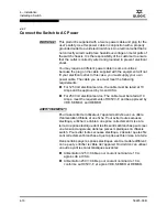
To power up the switch, connect the power cord to the AC power receptacle on
the back of the switch chassis and to a grounded AC outlet. The switch responds
in the following sequence:
1.
The chassis LEDs (Input Power, Heartbeat, System Fault) illuminate
followed by all port Logged-In LEDs.
2.
After a couple seconds the System Fault LED is extinguished while the Input
Power LED and Heartbeat LED remain illuminated.
3.
After one minute, the POST executes and the Heartbeat LED extinguishes.
4.
After about another minute, the POST is complete, all LEDs are
extinguished except the Input Power LED and the Heartbeat LED:
The Input Power LED remains illuminated indicating that the switch is
receiving DC voltage. If not, contact your authorized maintenance
provider.
The Heartbeat LED indicates the results of the POST. The POST tests
the condition of firmware, memories, data-paths, and switch logic. If
the Heartbeat LED blinks steadily once per second, the POST was
successful, and you can continue with the installation. Any other blink
pattern indicates an error. Refer to
“Heartbeat LED Blink Patterns” on
page 5-3
for more information about error blink patterns.
WARNUNG!!
Dieses Produkt wird mit einem 3-adrigen Netzkabel mit Stecker
geliefert. Dieses Kabel erfüllt die Sicherheitsanforderungen und
sollte an einer vorschriftsmäßigen Schukosteckdose
angeschlossen werden, um die Gefahr eines elektrischen
Schlages zu vermeiden.Elektrosteckdosen, die nicht richtig
verdrahtet sind, können gefährliche Hochspannung an den
Metallteilen des switch-Gehäuses verursachen. Der Kunde trägt
die Verantwortung für eine vorschriftsmäßige Verdrahtung und
Erdung der Steckdose zur Vermeidung eines elektrischen
Schlages.
In manchen Ländern ist eventuell die Verwendung eines anderen
Kabels erforderlich, da der Stecker des mitgelieferten Kabels nicht
in die landesüblichen Steckdosen paßt. In diesem Fall müssen Sie
sich ein Kabel besorgen, daß die folgenden Anforderungen erfüllt:
Für 125 Volt-Netze: 10 Ampere Kabel mit UL- und
CSA-Zulassung.
Für 250 Volt-Netze:
10 Ampere Kabel gemäß den
Anforderungen der H05VV-F und VDE-, SEMKO- und
DEMKO-Zulassung.
Summary of Contents for SANbox 1400 Series
Page 26: ...1 Introduction Technical Support 1 18 59225 00 B S Notes...
Page 46: ...3 Planning Fabric Management 3 10 59225 00 B S Notes...
Page 88: ...A Specifications Regulatory Certifications A 6 59225 00 B S Notes...
Page 200: ...B Command Line Interface Zoning Command B 112 59225 00 B S Notes...
Page 206: ...SANbox 1400 Series Fibre Channel Switch Installation Guide Glossary 6 59225 00 B S Notes...
Page 214: ...SANbox 1400 Series Fibre Channel Switch Installation Guide Index 8 59225 00 B S Notes...


