background image

3–Managing Switches

Installing Feature License Keys

3-42

59264-02  B

Figure 3-16. Features License Key Dialog Box

4.

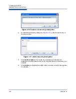
On the Add License Key


dialog box (

Figure 3-17

), enter the license key in 

the Key text box.

Figure 3-17. Add License Key Dialog Box

5.

Click 

Get Description

. The license key description is retrieved and 

displayed in the Description area you to verify that this is the license key you 
ordered. 

6.

Click 

Add Key

 to upgrade the switch. Allow a minute or two for the upgrade 

to complete. 


Summary of Contents for SANbox 5800V Series

Page 1: ...59264 02 B User s Guide QuickTools Switch Management 5800V Series Fibre Channel Switches Firmware Version 8 0...

Page 2: ...y time without notice Applications described in this document for any of these products are for illustrative purposes only QLogic Corporation makes no representation nor warranty that such application...

Page 3: ...3 Alerts Panel 1 5 Fabric Tree 1 6 Graphic Window 1 6 Data Windows and Tabs 1 6 Menu Bar 1 7 Shortcut Menus 1 8 Shortcut Keys 1 9 Selecting Switches 1 9 Selecting Ports 1 9 Setting QuickTools Prefere...

Page 4: ...2 21 Managing Device Port Nicknames 2 21 Creating a Nickname 2 22 Editing a Nickname 2 22 Deleting a Nickname 2 22 Exporting Nicknames to a File 2 23 Importing Nicknames from a File 2 23 Zoning 2 24 A...

Page 5: ...one Set 2 42 Removing a Zone from All Zone Sets 2 42 Managing Aliases 2 43 Creating an Alias 2 43 Adding a Member to an Alias 2 43 Removing an Alias from All Zones 2 44 Merging Fabrics and Zoning 2 44...

Page 6: ...SNMP Properties 3 29 SNMP Configuration 3 30 SNMP Trap Configuration 3 31 SNMP v3 Security 3 32 Archiving a Switch 3 34 Restoring a Switch 3 35 Testing a Switch 3 36 Restoring the Factory Default Con...

Page 7: ...Alerts Panel 1 5 1 5 Preferences Dialog Box QuickTools 1 11 2 1 TR Mapping Manager Dialog Box 2 7 2 2 Add TR Mapping Dialog Box 2 8 2 3 Remote Fabric Zoning Dialog Box 2 10 2 4 Transparent Routes Data...

Page 8: ...Box 3 52 3 24 Call Home Message Queue Dialog Box 3 53 3 25 Call Home Profile Manager Dialog Box 3 53 4 1 Port Information Data Window 4 1 4 2 Port Information Data Window Buttons 4 2 4 3 Port Statisti...

Page 9: ...eries Fibre Channel Switches 4 2 Port Statistics Data Window Entries 4 7 4 3 Port Properties Dialog Box Entries 4 11 4 4 Port Operational States 4 12 4 5 Port Administrative States 4 13 4 6 Port Types...

Page 10: ...x 59264 02 B User s Guide QuickTools Switch Management 5800V Series Fibre Channel Switches...

Page 11: ...an index are also provided Intended Audience This manual introduces the switch management products and explains their installation and use It is intended for users responsible for installing and usin...

Page 12: ...in the end user documentation provided with the redistribution and or in the software itself an acknowledgement equivalent to the following This product includes software developed by the JDOM Projec...

Page 13: ...tion on the left The QLogic Global Training portal offers online courses certification exams and scheduling of in person training Technical Certification courses include installation maintenance and t...

Page 14: ...n extensive collection of QLogic product information that you can search for specific solutions We are constantly adding to the collection of information in our database to provide answers to your mos...

Page 15: ...Version Exiting QuickTools Workstation Requirements The requirements for fabric management workstations running the QuickTools web applet are listed in Table 1 1 Table 1 1 Workstation Requirements Ope...

Page 16: ...dow is displayed Figure 1 3 For security reasons you will be prompted to change your user account password that was initially set up by the administrator Figure 1 2 You will be prompted to change the...

Page 17: ...above the switch names as a reference Click a switch name or icon on the fabric tree to display a different switch faceplate or backplate on the graphic window along with its corresponding data window...

Page 18: ...Interface 1 4 59264 02 B Figure 1 3 QuickTools Interface Data Window Tabs Graphic Window Fabric Tree Menu Bar Data Window Fabric Switch Name and Status QLogic 5802V Switch Backplate Display QLogic 580...

Page 19: ...etween the Alerts Panel entries and data windows enable you to move the divider bar up or down With the faceplate image and data windows displayed click the up arrow on left to move the divider up to...

Page 20: ...t the mouse on the fabric icon on the fabric tree Graphic Window The graphic window Figure 1 3 shows the switch faceplate or backplate display The window height can be adjusted by clicking and draggin...

Page 21: ...ing zones and their member ports Refer to Active Zone Set Data Window on page 2 25 for more information about this data window Refer to Zoning on page 2 24 for information about zone sets and zones Me...

Page 22: ...og boxes Port Port Properties Advanced Port Properties Reset Port Port Diagnostics Online Offline Zoning Edit Zoning Resolve Zoning Capture Active Zoning Restore Configured Zoning Capture Merged Zonin...

Page 23: ...port icon Refer to 4 Managing Ports for detailed port information Selected ports on the faceplate display are outlined in light blue You can select ports the following ways To select a port click the...

Page 24: ...ult you cannot open a fabric with a non secure connection Enable default or disable the Event Browser Refer to Event Browser on page 2 15 If the Event Browser is enabled using the Preferences dialog b...

Page 25: ...want 4 Click OK to save the changes Using Online Help The browser based online help system can be accessed from the QuickTools web applet several ways Online help is also context sensitive that is the...

Page 26: ...ewing Software Version 1 12 59264 02 B Viewing Software Version To view the QuickTools software version information on the Help menu click About Exiting QuickTools To exit a QuickTools web applet sess...

Page 27: ...ity string private are set at the factory to these well known defaults and should be changed if SNMP is enabled using the System Services or SNMP Properties dialog boxes If SNMP is enabled default and...

Page 28: ...ation being displayed and rediscovers all switch information To rediscover a fabric on the Fabric menu click Rediscover Fabric The rediscover function is more comprehensive than the refresh function A...

Page 29: ...e Restore menu item is not available for the in band switches You can only restore a switch out of band the fabric management switch There are certain parameters that are not archived and these are no...

Page 30: ...paste the zoning commands automatically generated by TR Mapping Manager into the remote fabric management application The local QLogic fabric may consist of one or multiple switches connected by their...

Page 31: ...Port ID Virtualization NPIV and for Brocade fabrics the interoperability mode must be configured to InteropMode 0 The TR_Port logs into the remote fabric using the WWN of the TR_Port The TR_Port acce...

Page 32: ...led information for that TR mapping member in the Selected TR Mapping area NOTE Since Cisco switches do not support the Unzoned Name Server Cisco fabrics must be pre zoned before you can set up TR map...

Page 33: ...e zone set is activated If there are no TR mappings the old IFZs are deleted from the active zone set and then the active zone set is re activated If there are no zones and no IFZs in the active set t...

Page 34: ...e Add TR Mapping dialog box appears after you click Add or on the Edit menu click Add in the TR Mapping Manager dialog box Select a local device from the 1 Select a Local Device column to display the...

Page 35: ...g members appear in the TR Mapping list of the TR Mapping Manager dialog box and then click OK NOTE The local fabric port to be used in the inter fabric zone must be configured as a TR_Port before the...

Page 36: ...oning commands to generate for the user Fabrics with Brocade and Cisco switches are supported Figure 2 3 Remote Fabric Zoning Dialog Box To create a zoning commands text file for the remote fabric 1 O...

Page 37: ...es 7 Enter the Configuration Name which is used as the zone set name in the commands This must be the same zone set name as the zone set on the remote fabric to which this zoning will be applied or el...

Page 38: ...ame path name will overwrite the first path name 10 Click Save to save the zoning commands text file on your workstation NOTE If the commands are run and the Configuration Name is not the name of the...

Page 39: ...Route Route number reference for each listing in the Transparent Routes data window table State The current TR mapping state Active or Inactive Active Indicates that the mapping s TR port is on this...

Page 40: ...are displayed for both sides of the route Device A will not necessarily correspond to the switch side of the route as the end points of the route could be in any order Figure 2 5 Transparent Route Dia...

Page 41: ...th the new events Event entries from the switch use the switch time stamp while event entries generated by the web applet have a workstation time stamp You can filter sort and export the contents of t...

Page 42: ...al event an event that indicates a potential failure Critical log messages are events that warrant notice by the user By default these log messages will be posted to the screen Critical log messages d...

Page 43: ...t one or both of the From and To options Enter the bounding timestamps MM DD YY HH MM AA to display only those events that fall within those times AA indicates AM or PM The current year YY can be ente...

Page 44: ...or By Description Successive sort operations of the same type alternate between ascending and descending order Saving the Event Browser to a File You can save the displayed Event Browser entries to a...

Page 45: ...n place of the World Wide Name This sub section describes how to view and manage device information and nicknames Devices Data Window Displaying Detailed Device Information Managing Device Port Nickna...

Page 46: ...on the Edit Nickname dialog box Refer to Managing Device Port Nicknames on page 2 21 for more information Details Click the i to display additional information about the device Refer to Displaying De...

Page 47: ...to a world wide name of a device Assigning a nickname makes it easier to recognize device ports when zoning your fabric or when viewing the Devices data window You can add edit delete import and expor...

Page 48: ...Nicknames dialog box 4 Click Save to save the changes Editing a Nickname To edit a device port nickname do the following 1 On the Fabric menu click Nicknames to view the Nicknames dialog box The devic...

Page 49: ...to an XML file do the following 1 On the Fabric menu click Nicknames to view the Nicknames dialog box 2 On the File menu click Export 3 Enter a name for the XML nickname file on the Save dialog box a...

Page 50: ...ric into zones for more efficient and secure communication among functionally grouped nodes This section addresses the following topics Active Zone Set Data Window Configured Zonesets Data Window Zoni...

Page 51: ...dow The Active Zoneset data window uses display conventions for expanding and collapsing entries that are similar to the fabric tree An entry handle located to the left of an entry on the tree indicat...

Page 52: ...y conventions for expanding and collapsing entries that are similar to the fabric tree An entry handle located to the left of an entry on the tree indicates that the entry can be expanded Click this h...

Page 53: ...an one zone set Several zone sets can be defined for a fabric but only one zone set can be active at one time The active zone set determines the current fabric zoning Membership in a zone can be defin...

Page 54: ...taining one or more zone sets This zoning database resides in non volatile or permanent memory and is therefore retained after a reset Refer to Configured Zonesets Data Window on page 2 26 for informa...

Page 55: ...ets that can be configured on the switch MaxZones is 2000 The maximum number of zones that can be configured on the switch including orphan zones MaxAliases is 2500 The maximum number of aliases that...

Page 56: ...lick Properties 3 View the zoning properties information on the Properties dialog box 4 Click OK to close the Properties dialog box Managing the Zoning Database Managing the zoning database consists o...

Page 57: ...you activate a zone set the switch distributes that zone set and its zones excluding aliases to every switch in the fabric This zone set is known as the active zone set You cannot edit an active zone...

Page 58: ...ool bar operations Use the Edit Zoning dialog box to define zoning changes and click Apply to view the Error Check dialog box Click Error Check to have QuickTools check for zoning conflicts such as em...

Page 59: ...om a zone Copy button copies selected zoning items to clipboard Paste button pastes clipboard items to selected zoning item where applicable Switch port icon not logged in Switch port icon logged in N...

Page 60: ...ured zone set View Merged Configured Differences The View Merged Configured Differences option opens a dialog box to display the Merged and Configured zone sets in split panes The items in the Merged...

Page 61: ...fabric If interop mode is not Standard mode the Default Zone parameter is automatically distributed throughout the fabric Discard Inactive The Discard Inactive parameter automatically removes inactive...

Page 62: ...the Zoning menu click Edit Zoning to view the Edit Zoning window 2 On the File menu click Reload from the Source 3 Click OK to load the original zoning database configuration to the switch Restoring t...

Page 63: ...nly one zone set can be active at one time Managing zone sets consists of the following tasks Creating a Zone Set Activating and Deactivating a Zone Set Copying a Zone to a Zone Set Removing a Zone Se...

Page 64: ...he active zone set before activating a new one To activate a zone set on the Zoning menu click Activate Zone Set to view the Activate Zone Set dialog box Select a zone set from the Select Zone Set dro...

Page 65: ...rom a Zone Set Removing a Zone from All Zone Sets Creating a Zone in a Zone Set To create a zone in a zone set do the following 1 On the Zoning menu click Edit Zoning to view the Edit Zoning dialog bo...

Page 66: ...Zoning dialog box 2 On the zone set tree select the zone to copy and click Copy 3 Select the destination zone set and click Paste 4 Click Apply to display the Save Zoning Error Check dialog box 5 Clic...

Page 67: ...rst Port Address option d Enter the hexadecimal value for the port device according to the option selected 16 digits for a WWN member 4 digits for a Domain Port member DDPP or a 6 digit Fibre Channel...

Page 68: ...o save the change 5 Click Close to close the Edit Zoning dialog box Removing a Zone from a Zone Set To remove a zone from a zone set do the following 1 On the Edit Zoning dialog box select the zone to...

Page 69: ...he following 1 On the Zoning menu click Edit Zoning to view the Edit Zoning dialog box 2 Choose one of the following methods to add the port device Select a port device on the Port Device tree and dra...

Page 70: ...connected together The switches in the two fabrics attempt to create a new active zone set containing the union of each fabric s active zone set The propagation of zoning information only affects the...

Page 71: ...accurately defines your zoning needs If not you must edit the zone memberships and reactivate the zone sets After correcting the zone membership reset the isolated ports to allow the fabrics to join R...

Page 72: ...2 Managing Fabrics Zoning 2 46 59264 02 B Notes...

Page 73: ...User Accounts Paging a Switch Setting the Date Time and Enabling NTP Client Resetting a Switch Configuring a Switch Configuring the Network Configuring SNMP Archiving a Switch Restoring a Switch Testi...

Page 74: ...tch To view the Switch data window click the Switch tab below the data window Figure 3 1 Switch Data Window Information on the Switch data window is grouped and accessed by the Summary Status Network...

Page 75: ...ed to each chassis Reason for Status The reason for the operational state Vendor Switch manufacturer MAC Address Media Access Control address Negotiated Domain ID The domain ID currently being used by...

Page 76: ...Fan 2 status Power Supply 1 Status Power supply 1 status Power Supply 2 Status Power supply 2 status Temperature Failure Port Shutdown Non configurable always enabled for this switch All ports are dow...

Page 77: ...tatus Broadcast support is enabled default or disabled NTP Client Enabled Enabled or disabled Allows for switches to synchro nize their time to a centralized server NTP Server Address The IP address o...

Page 78: ...through the fabric using Name Ser vice Management Server functions QuickTools will report all FDMI information reported by the entry switch if FDMI is enabled on the entry switch FDMI HBA Entry Limit...

Page 79: ...bric will be saved only in temporary memory and will be lost after a switch reset Zoning Default Visibility N A does not apply to this switch Default Zone Disables communication between ports and devi...

Page 80: ...time out threshold In band Enabled In band management status Permits True or pre vents False a switch from being managed over an ISL Principal Switch If there is a domain ID conflict in the fabric the...

Page 81: ...min account is the only user that can manage all user accounts with the User Account Administration dialog boxes The Admin account can create remove or modify user accounts and change account password...

Page 82: ...tab page 3 Enter an account name in the New Account Login text box Account names are limited to 15 characters The first character must be alphanumeric 4 If the account is to have the ability to modify...

Page 83: ...n the Switch menu click User Accounts Click the Remove Account tab on the User Account Administration dialog box to present the display Figure 3 4 Select the account login name from the list of accoun...

Page 84: ...name from the list of accounts at the top of the dialog box then enter the old password the new password and verify the new password in the corresponding text boxes Click Change Password Any user can...

Page 85: ...elect the account login name from the list of accounts at the top of the dialog box Select the Admin Authority Enabled option to grant admin authority to the account name Select an Account Expiration...

Page 86: ...selected the Date and Time areas becomes inactive thus preventing you from manually setting the date and time on the switch The NTP Server Discovery list and NTP Server IP Address text box become act...

Page 87: ...rations that change the fabric include Zoning modifications Adding moving or removing devices attached to the switch fabric This includes powering up or powering down attached devices Adding moving or...

Page 88: ...rd The Configuration Wizard is a series of dialog boxes that guide you through the steps to configure new or replacement switches Using the Configuration Wizard The Configuration Wizard is a series of...

Page 89: ...ch Administrative States Broadcast Support In band Management Fabric Device Management Interface To view the Switch Properties dialog box choose one of the following On the faceplate display for the s...

Page 90: ...h will isolate as a separate fabric However you can remedy this by resetting the new switch or taking it offline then back online The principal switch will reassign the domain ID and the switch will j...

Page 91: ...x Current administrative state the state that is applied to the switch for temporary purposes and is not retained across switch resets The current administrative state is set using the Set Switch comm...

Page 92: ...device interface enables a device s management information to be registered The application to fabric interface provides the framework by which an application obtains device information from the fabri...

Page 93: ...anges click OK to put the new values into effect Figure 3 8 Advanced Switch Properties Dialog Box Timeout Values The switch timeout values determine the timeout values for all ports on the switch The...

Page 94: ...and Call Home To display the System Services dialog box on the Switch menu click Services Figure 3 9 System Services Dialog Box NOTE System services requiring you to enter an IP address are dependant...

Page 95: ...s time and date settings from an NTP server Configuring all of your switches and your workstations to utilize NTP will keep their date time settings in sync and will prevent difficulties with SSL cert...

Page 96: ...ies IP dialog box Click the DNS tab to view the Network Properties DNS dialog box After making changes click OK to put the new values into effect To view the Network Properties dialog box choose one o...

Page 97: ...address An IPv6 address is 128 bits and consists of eight blocks of hexadecimal numbers with each block separated by a colon The maximum number of numerals in each block is four One or more blocks wit...

Page 98: ...Resolution Proto col acquires the IP address from a RARP server A RARP request is broadcast with up to three retries each at 5 second intervals If no IP address is obtained the switch reverts to the p...

Page 99: ...namic Host Configuration Protocol ver sion 6 acquires the IP configuration from a DHCP server If no satisfactory lease is obtained the DHCP client attempts to use the previously configured lease If th...

Page 100: ...onflict DNS Server Addresses The IP address of the DNS server DNS Search List Search List Discovery Choose one of the following methods by which to assign the IP address Static uses the IP configurati...

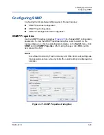
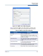
Page 101: ...11 to change SNMP configuration parameters To view the SNMP Properties dialog box select a switch on the topology display or on the faceplate backplate display on the Switch menu click SNMP and click...

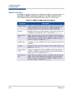
Page 102: ...ned Read Commu nity Read community password up to 32 characters that authorizes an SNMP agent to read information from the switch This is a write only field The value on the switch and the SNMP manage...

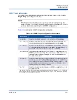
Page 103: ...be unique For example if trap 1 and trap 2 have the same address then they must have different port values Similarly if trap 1 and 2 have the same port value they must have different addresses Specifi...

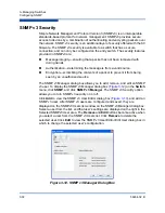
Page 104: ...t to prevent it from being seen by an unauthorized source The SNMP v3 Manager dialog box allows you to add remove and edit an SNMP v3 user To display the SNMP v3 Manager dialog box Figure 3 12 on the...

Page 105: ...user Group Read Only permits user to view only SNMP v3 user settings Read Write permits user to view and change SNMP v3 user settings Authentication Type None MD5 SHA If None no authentication phrase...

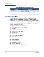
Page 106: ...g the CLI after a restore To archive a switch do the following 1 On the Switch menu click Archive 2 On the Save dialog box enter a file name 3 Click Save Archived parameters include the following Swit...

Page 107: ...Series switch archive Refer to Archiving a Switch on page 3 34 for more information To restore a switch do the following 1 Log in to the fabric through the switch you want to restore You cannot resto...

Page 108: ...es all settings presented on the Switch properties dialog box except the domain ID Refer to Switch Properties on page 3 17 Domain ID restores switch domain ID in addition to the other switch propertie...

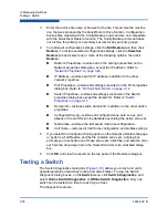
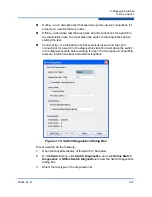
Page 109: ...t exercises all port and inter port connections for a switch in the diagnostics state You must place the switch in the diagnostics state before starting the test The two types of connectivity tests ar...

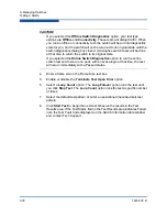
Page 110: ...Failed note the Test Fault Code displayed on the Switch Information data window and contact Tech Support CAUTION If you selected the Offline Switch Diagnostics option your test type options are Offlin...

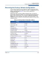
Page 111: ...ser accounts you must select the Reset User Accounts to Default option in the maintenance menu Refer to Recovering a Switch in the Installation Guide for your switch for information about maintenance...

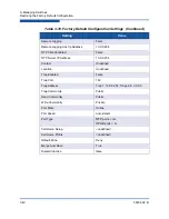
Page 112: ...Undefined Trap Enabled False Trap Port 162 Trap Address Trap 1 10 0 0 254 Traps 2 5 0 0 0 0 Trap Community Public Read Community Public Write Community Private Port State Online Port Speed Auto detec...

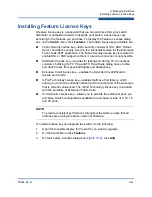
Page 113: ...s of utilizing the FC Ping and FC TraceRoute dialog boxes to time and track frames from specified targets and destinations Extended Credit license key enables the Extended Credit Wizard to donate port...

Page 114: ...box Figure 3 17 enter the license key in the Key text box Figure 3 17 Add License Key Dialog Box 5 Click Get Description The license key description is retrieved and displayed in the Description area...

Page 115: ...nstalling firmware involves loading unpacking and activating the firmware image on the switch QuickTools does this in one operation To provide consistent performance throughout the fabric ensure that...

Page 116: ...installed The default path to search for firmware image files is the user s working directory To change the path click Browse and specify a new path Click Rescan to search the folder displayed in the...

Page 117: ...splay the Call Home Setup dialog box on the Switch menu click Call Home and click Setup Figure 3 19 Call Home Setup Dialog Box Table 3 11 lists the entries on the Call Home Setup dialog box Table 3 11...

Page 118: ...secondary second SMTP server Secondary SMTP Server Port The service port number that the secondary SMTP server is listening on to accept connection from SMTP sending agents Contact Email Address The...

Page 119: ...rom address ReplyTo Email Address The Email address used by mail reading programs to determine the address that an Email should be addressed to for a reply to a received message This value will over r...

Page 120: ...ialog box on the Switch menu click Call Home and click Profile Manager The Profiles list shows all profiles on the switch The Email List shows all Email addresses associated with the selected profile...

Page 121: ...type for the message text being sent short full tsc1 enter the size of the message being sent enter the subject of the Email and enter the Email address es of the recipients Click Add to add the Email...

Page 122: ...r on the Call Home Profile Manager dialog box or on the Edit menu click Create Tech Support Center Profile The name on the title bar changes to reflect the Tech Support profile function create or edit...

Page 123: ...tes allowed for a Email mes sage compiled for the profile Most Email messages are relatively small under 2KB However Emails that are pro duced by a capture operation can be as large as 1MB due to the...

Page 124: ...ive any profiles The Selected Switches list shows the switch names that you selected to receive all profiles from the switch On the Available Switches list select the switches in the fabric to receive...

Page 125: ...ormation Click Clear Queue to clear the current statistics Figure 3 24 Call Home Message Queue Dialog Box Testing Call Home Profiles Use the Call Home Test Profile dialog box Figure 3 25 to test the C...

Page 126: ...3 54 59264 02 B Change Over Changes the inactive SMTP server to become the active SMTP server To make the inactive SMTP become the active SMTP on the Switch menu click Call Home and click Change Over...

Page 127: ...d devices Port Information Data Window Port Statistics Data Window Viewing and Configuring Ports Resetting a Port Testing Ports Port Information Data Window The Port Information data window Figure 4 1...

Page 128: ...e administrative port type G GL F FL or Donor This value is persistent it will be maintained during a switch reset Dur ing port auto configuration it will be used to determine which operational port s...

Page 129: ...is isolated Administrative Port Speed The speed requested by the user Operational Port Speed The speed actually being used by the port Port Speed Supported The speeds supported by the port Symbolic N...

Page 130: ...Downstream ISL The ISL over which the switch has received requests intended for the princi pal switch Extended Credits Group Extended Credits Requested Number of requested credits Max Credits Availabl...

Page 131: ...electrical Media Distance The maximum transceiver transmission distance Media Vendor The company that manufactured the SFP Media Vendor ID The IEEE registered company ID Media Part Number The part num...

Page 132: ...a window and provides different ways to view detailed port information Click the down arrow to view the drop down list On the drop down list select Absolute to view the total count of statistics since...

Page 133: ...ber of times more frames were lost during a credit recovery period than the recovery process could resolve This causes a Link Reset to recover the credits BB_CreditRecoveryR RDYFailure Number of times...

Page 134: ...ress identifier S_ID D_ID errors AL_PA equals non zero AL_PA found on F_Port Link Failures Number of optical link failures detected by this port A link fail ure is a loss of synchronization or by loss...

Page 135: ...ors Total number of primitive and non primitive port link errors Total Link Resets Number of link reset primitives transmitted and received by the port Total LIPs Received Number of loop initializatio...

Page 136: ...a port icon on the faceplate display Use the drop down lists on the Port Properties dialog box to change the following parameters Port Symbolic Name Port States Port Types Port Speeds Port Transceive...

Page 137: ...rt type that is currently active Configured Type The port type saved in the switch configuration To change click in the text box and select an option from the drop down list I O Stream Guard The I O S...

Page 138: ...wo forms the configured administrative state and the current administrative state Refer Port Administrative States on page 4 13 to for more information Port Operational States To view the operational...

Page 139: ...following 1 Select one or more ports on the faceplate display 2 On the Port menu click Port Properties to view the Port Properties dialog box 3 Select the Port State option from the drop down list 4...

Page 140: ...s only G_Port Generic port self discovers as an F_Port or an E_Port GL_Port Generic loop port self discovers as an F_Port FL_Port or an E_Port GL_Port is the default port type A single device on a pub...

Page 141: ...display 2 On the Port menu click Port Properties to view the Port Properties dialog box 3 Select the Port Speed option from the drop down list 4 Click OK to write the new port speed to the switch Tab...

Page 142: ...logged in active and ready to send data Optical SFP offline gray black not logged in active can receive sig nal but cannot accept a device login Optical SFP unlicensed dark gray black Optical SFP unkn...

Page 143: ...t the option that corresponds to one of the following options Enable suppresses the reception of RSCN messages from other ports for which I O Stream Guard is enabled Disable allows free transmission a...

Page 144: ...s option applies only affects ports running in loop FL mode To view the Advanced Port Properties dialog box select one or more ports on the Port menu click Advanced Port Properties Figure 4 5 Advanced...

Page 145: ...fore disrupts communication External a disruptive test that verifies port circuitry The SFP level test sends a test frame from the ASIC through the SerDes chip through the SFP transceiver fitted with...

Page 146: ...gnostic state Click OK and you will be prompted to change the port state 4 Enter the frame count frame size and select a test pattern option You may use the default pattern or enter an 8 digit pattern...

Page 147: ...hysical Address Arbitrated Loop A Fibre Channel topology where ports use arbitration to establish a point to point circuit Arbitrated Loop Physical Address AL_PA A unique one byte value assigned durin...

Page 148: ...ools session Fan Fail LED An LED that indicates that a cooling fan in the switch is operating below standard FCID Fibre Channel Identifier The value that identifies a device on the fabric Flash Memory...

Page 149: ...cted to each other chassis in the fabric MIB Management Information Base Multistage Topology A fabric in which two or more edge switches connect to one or more core switches NL_Port Node Loop Port A F...

Page 150: ...abric TR_Ports do not support online port diagnostics User Account An object stored on a switch that consists of an account name password authority level and expiration date VCCI Voluntary Control Cou...

Page 151: ...0 C Call Home 3 23 Common Interface Model service 3 23 configuration archive 3 34 restore 3 35 wizard 3 16 configured administrative state 3 19 Configured Zonesets data window 2 26 contact 3 30 curren...

Page 152: ...24 Fabric Device Management Interface 3 20 factory defaults 3 39 FC 4 descriptor 4 17 FDMI See Fabric Device Management Interface feature license key 3 41 File Transfer Protocol service 3 23 FL_Port...

Page 153: ...4 19 transceiver 4 16 type 4 13 view 1 10 4 10 Port Information data window 4 1 Port Statistics data window 4 6 port device tree 2 32 principal switch 3 18 processor 1 1 properties network 3 29 Q Quic...

Page 154: ...window 3 2 symbolic name port 4 12 switch 3 19 syslog 3 18 system services 3 22 T Telnet service 3 23 testing ports 4 19 The 2 38 time 3 14 timeout values 3 21 tool bar zoning 2 32 transceiver status...

Page 155: ...ve member port 2 42 rename 2 38 2 42 zone merge description 2 44 failure 2 44 failure recovery 2 45 zone set activate 2 38 active 2 25 2 28 create 2 37 deactivate 2 38 definition 2 28 discard inactive...

Page 156: ...User s Guide QuickTools Switch Management 5800V Series Fibre Channel Switches Index 6 59264 02 B...

Page 157: ......

Page 158: ...tered trademark of Linus Torvalds Mac OS X and Safari are registered trademarks of Apple Computer Inc Microsoft Windows XP Windows 2003 and Internet Explorer are trademarks of Microsoft Corporation Ne...

Reviews: