QS series manual v3.09
QMAXZ © 2009
- 8 -
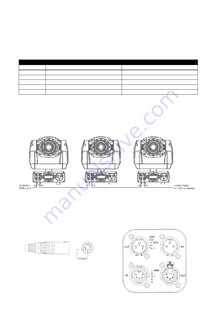
6.3 Signal Connection
Important! Never connect more than 1 data input and 1 data output.
The QMAXZ fixtures have both 3 and 5 pin XLR sockets. The sockets are wired parallel, both inputs
connect to both outputs. Never use 3 and 5 pin connectors at the same time. For the pin-layout see
the following table.
Pin-Layout
Pin
5 pin
3 pin
1 Earth
Earth
2
Signal – (Cold)
Signal – (Cold)
3
(Hot)
(Hot)
4 No
connection
5 No
connection
Use a shielded twisted pair cable suitable for RS485 (120
Ω
) operation at 250 baud
Microphone type and other general purpose cabling such as two core audio or signal cables are not
suitable for use with DMX512.
Connect the DMX output from the controller to the closest fixture input and connect the fixture DMX
output to the next fixture DMX input until all fixtures are connected.
Do not overload the link. A maximum of 10 devices may be connected on a serial link.
Insert a male 120
Ω
XLR termination plug, in the last fixture. This to avoid signal reflection and
interference.
DMX Terminator
DMX connection panel
Summary of Contents for QS Series
Page 2: ...QS series manual v3 09 QMAXZ 2009 1...
Page 11: ...QS series manual v3 09 QMAXZ 2009 10 7 2 Function Menu QS250S...
Page 12: ...QS series manual v3 09 QMAXZ 2009 11...
Page 13: ...QS series manual v3 09 QMAXZ 2009 12...
Page 14: ...QS series manual v3 09 QMAXZ 2009 13...
Page 16: ...QS series manual v3 09 QMAXZ 2009 15...
Page 17: ...QS series manual v3 09 QMAXZ 2009 16 7 3 Function Menu QS250W...
Page 19: ...QS series manual v3 09 QMAXZ 2009 18 7...
Page 20: ...QS series manual v3 09 QMAXZ 2009 19...
Page 21: ...QS series manual v3 09 QMAXZ 2009 20...
Page 29: ...QS series manual v3 09 QMAXZ 2009 28 10 3 Dimensional Drawings...


